PASS/EQUIP → Working with PASS/EQUIP → Data input → Nozzle
Fig. 1. Nozzle
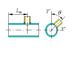
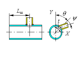
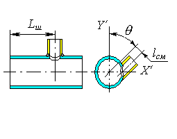
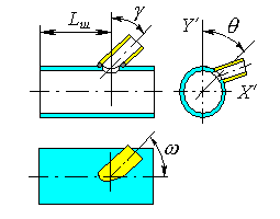
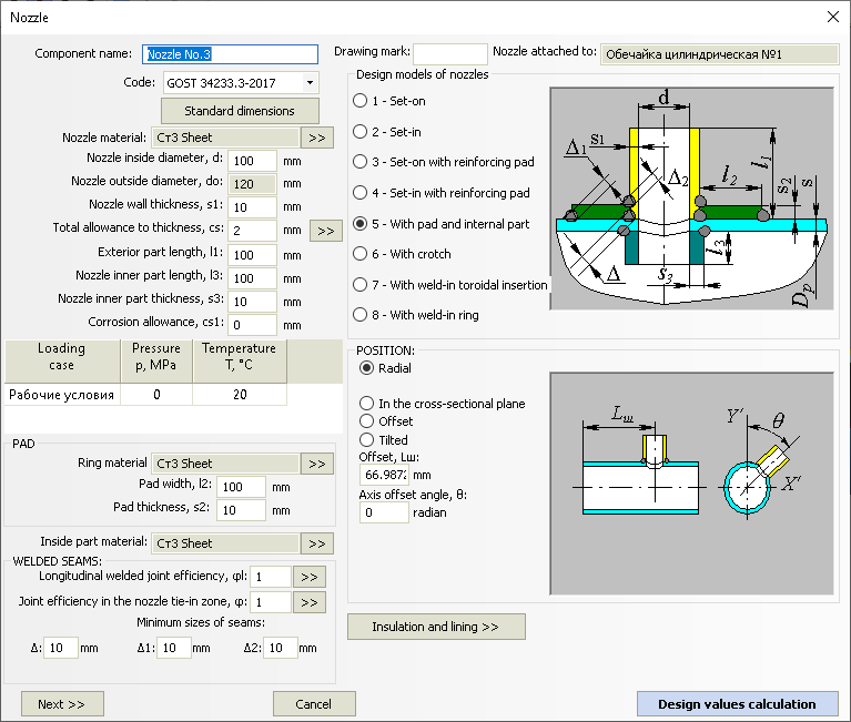
Component name, code of standards, material, dimensions, and weld strength factors for nozzles and padding ring (if present), as well as load properties, are set in the same way as those for cylindrical shells. Nozzle placement is determined based on the type of adjoining component. For cylindrical and conical shells and for conical heads, the nozzle can be radial (Fig. 2-a), positioned in the cross-sectional plane (Fig. 2-b), offset (Fig. 2-c), or placed arbitrarily (Fig. 2-d).
|
|
| (a) Radial | (b) In the cross-section plane |
|
|
| (c) Offset | (a) Tilted |
Fig. 2. Nozzle positioning on the cylinder
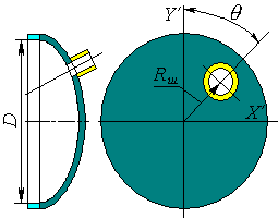
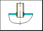
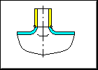
For dished heads (including spherical without knuckle), nozzle can be set in the polar or Cartesian coordinate system and can be radial, positioned along vessel’s axis or positioned arbitrarily (Fig. 3). For flat heads, nozzles must be placed perpendicular to surface.
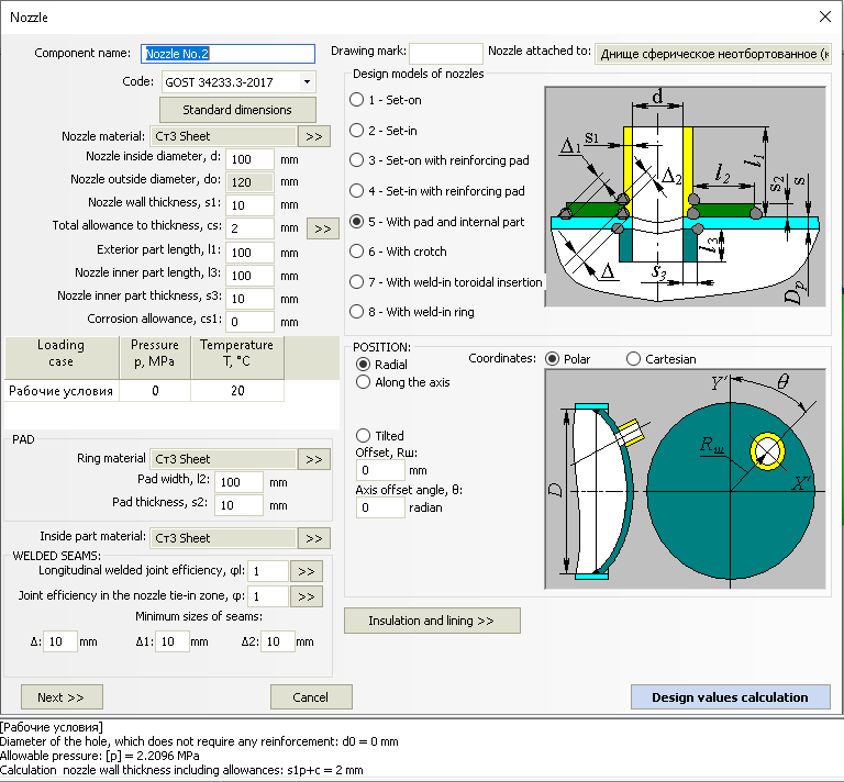
Fig. 3. Nozzle on the head
|
|
|
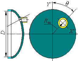
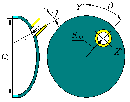
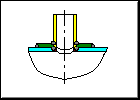
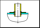
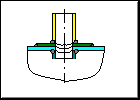
| Radial | Along the axis | Tilted |

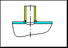
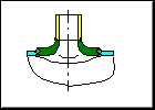
Fig. 3. Inward forming nozzle
For a set-in nozzle with the inner surface of the shell, select the "Set-in" configuration and set l3=0.
For an inward forming nozzlr (Fig. 3) set a negative value of “x”. .
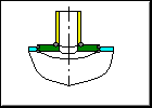
Fig. 3a. Nozzle positioning on the head
Nozzle model is determined according to GOST 34233.4-2017 (GOST 24755-89). See Fig. 5 for possible models.
|
|
|
|
| Set-on | Set-in | Set-on with reinforcing pad | Set-in with reinforcing pad |
|
|
|
|
| With pad and internal part | With crotch | With weld-in toroidal insertion | With weld-in ring |
Fig. 5. Nozzle types
An analysis of insertion point strength from external forces and moments
(assigned using the  button) is available for radially
placed nozzles in cylindrical and conical shells and dished heads.
button) is available for radially
placed nozzles in cylindrical and conical shells and dished heads.
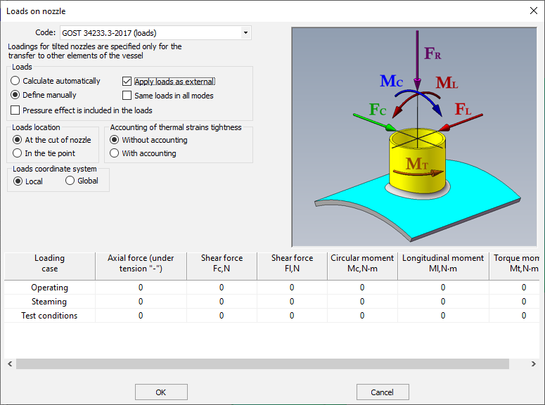
Fig. 6. Nozzle loads
In this case, in addition to nozzle reinforcing against pressure, an analysis of external forces and moments is carried out according to the selected standard (GOST 34233.3-2017 or RD 26.260.09-92) or the methods of WRC 537(107)/297, EN 13445-3.
Loads can be determined automatically during analysis based on the adjoining
component or set manually. If  is selected,
input loads on the nozzle will be transferred to all model components.
is selected,
input loads on the nozzle will be transferred to all model components.
The “Same loads in all modes” option allows you to avoid filling the whole table of loads individually for each mode if the loads are the same or differ slightly.
Using the “Loads coordinate system” option, loads can be specified in the nozzle coordinate system (“Local”) or in the model coordinate system (“Global”).
When manually assigning loads, a user can also specify, at what point they are applied (option "Location of loads"). When assigning loads on the nozzle cut, they are automatically recalculated during the calculation, taking into account length l1.
For flat head, operability under pressure is evaluated considering presence of passages.
Pay attention to positive and negative signs when setting forces and moments. Positive values correspond to directions indicated on the model. Analytical model displayed in Fig. 6 is applicable only for radial nozzles. For other variants of structure it is necessary to control the direction of loads on the displayed model, as in general the coordinate system of nozzle is set at an angle q first, then at w, and then at g or y. For instance, a shifted nozzle is resulted from the tilted nozzle, at w = 90°.
At calculation of loads using FEM method, cut-in is represented as several beam elements (Fig. 7):
External loads are applied to point 1 or 2, depending on the selected position.
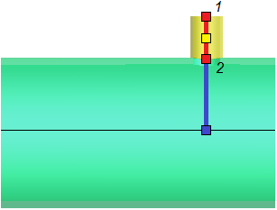
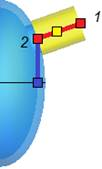
Fig. 7. Modeling a nozzle with beam elements