PASS/EQUIP → Working with PASS/EQUIP → Data input → Bend
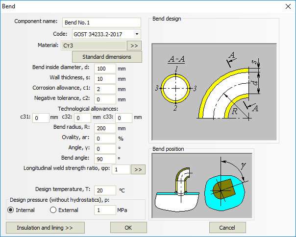
Fig. 1. Bend
Component name, material, dimensions, weld strength factors and load properties are set in the same way as those for cylindrical shells. Bends are connected to nozzles and their adjoining shells. Bend placement is determined by its bend angle.
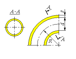
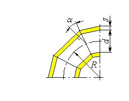
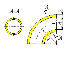
Bend design is determined according to SA 03-003-07. Available bends types are shown on Fig. 2.
The bend angle is limited to 90В°. To model U-bends, two bends must be used.
|
|
| (a) Seamless | (b) Sectorial |
|
|
| (c) Welded, when the welds are positioned in the curve plane | (d) Welded, when the welds are positioned along the neutral line |
Fig. 2. Bend types