PASS/EQUIP → Working with PASS/EQUIP → Data input → Flange joint
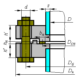
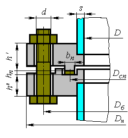
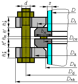
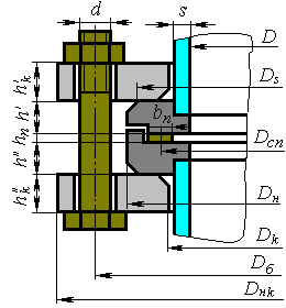
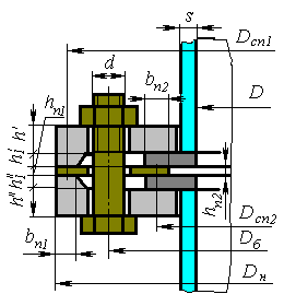
Fig. 1. Flange joint
Calculation of flange joints is possible as per RD 26-15-88, GOST 34233.4 -2017, ASME VIII div.1, ASME VIII div.2, EN 13445-3. Comparison of codes for consideration of loads is specified below:
Table 1
| Code | Pressure consideration | Consideration of external loads (F, M) | Consideration of temperature loads |
| RD 26-15-88 | + | + | + |
| GOST 34233.4 -2017 | + | + | + |
| ASME VIII div.1 | + | – | – |
| ASME VIII div.2 | + | + | – |
| EN 13445-3 | + | + | – |
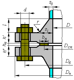
Component name, code of standards, material, dimensions and load properties for flanges are set in the same way as those for cylindrical shells. Flange type is determined according to GOST 12820(12821,12822)-80 (see Fig. 2).
|
|
|
|
|
|
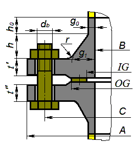
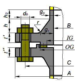
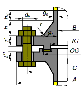
Fig. 2. Flange joint types
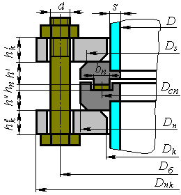
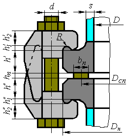
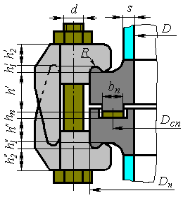
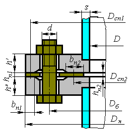
Fig. 3 - Fig. 7 show various flange joint models as per GOST 34233.4-2017.
|
|
| (a) Raised face | (b) Male-Female |
|
|
| (c) Tongue-Grove | (d) Ring Type Joint |
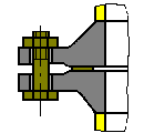
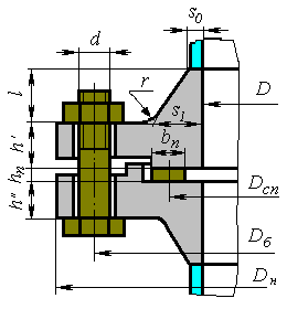
Fig. 3. Butt-welded flanges according to GOST 28759.3-90 (a,b,c) and GOST 28759.4-90 (d)
|
|
|
| (b) Raised face | (b) Male-Female | (c) Tongue-Grove |
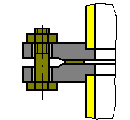
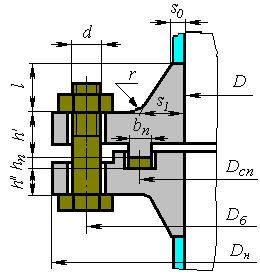
Fig. 4. Flat welded flanges according to GOST 28759.2-90
|
|
|
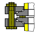
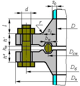
Fig. 5. Flanges with free rings
|
|
| (a) Flat face | (b) Tongue-Grove |
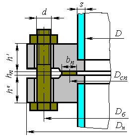
Fig. 6. Flanges for fasteners according to OST 26-01-396-78
|
|
| (a) | (b) |
Fig. 7. Contact flanges
Surface design of the flange joint at calculation as per ASME VIII-1(2) is shown in Fig. 8.
|
|
|
|
Fig. 8. Flange joint types as per ASME
Size of flanges, fasteners and gaskets can be selected from the database of standard parts by selecting the flange joint type and variation and pressing the "Dimensions according to ND" button. These properties will be set for both flanges.
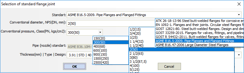
Fig. 9. Standard flange joint selection
To select a gasket from the database, its material must first be selected. Gasket type must match flange type to allow the selection of a standard part.
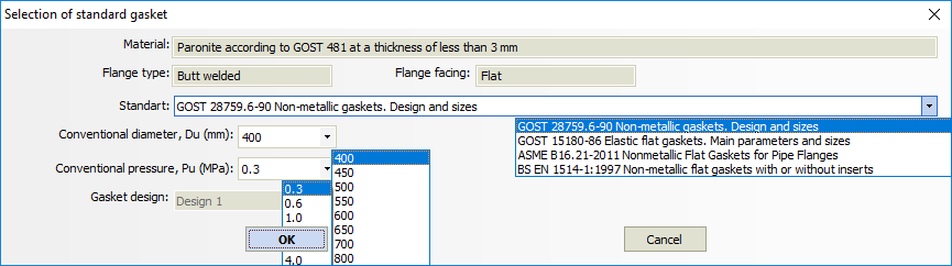
Fig. 10. Standard gasket selection
Dialog window (Fig. 10) may differ from the example, as it is determined by the flange joint type, its variation and the gasket material selected.
Bolt (stud) materials and properties can be selected from the database or input manually.
Pressing key  , you can open a dialog of extended
properties of flanges and fasteners (Fig. 11):
, you can open a dialog of extended
properties of flanges and fasteners (Fig. 11):
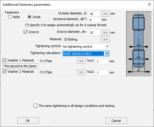
Fig. 11. Fasteners additional parameters
Item Groove is used for rods with groove diameter less than the
internal threading diameter. Flange insulation ( )
affects the temperature of flange joint components.
)
affects the temperature of flange joint components.
Selection of option “Control per moment” activates checkbox “Calculation of bolting load without allowance for minimum initial tension of bolts (0.4*[б]*Ab)”, which can be considered as deviation from GOST 34233.4-2017, but in some cases it helps avoiding of excessive reinforcement of flanges.
If you select item "Uniform tightening under operating conditions and tests", bolting load will be taken the same (maximum of all) for all modes.
The “Tightening calculation” option allows you to select an alternative standard for calculating the torque on the wrench.
Flange joint gasket and its properties can be selected from the RD 26-15-88
database or input manually by pressing  .
.
Database of materials of flanges and bolts is sensitive to the selected calculation code. This is due to the fact that ASME II Part D includes a large volume of data per allowable stresses, which can be used only in calculations as per ASME VIII-1(2).
Flange insulation influences on calculation temperatures of flange joint components, weight and material consumption.
Checkbox  is used for the part clamped between
the flanges (line-blanks, blind, etc).
is used for the part clamped between
the flanges (line-blanks, blind, etc).
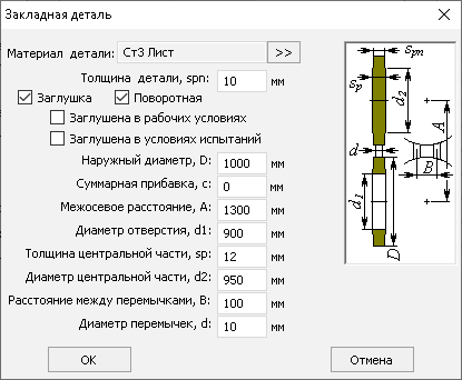
Fig. 12. Insertion
Item “Make more precise” allows more detailed assigning of parameters of the flange sealing surfaces (Fig. 13).
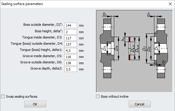
Fig. 13. Sealing surfaces
Option "Rearrange sealing surfaces" allows exchanging "male-female”.
The “Flange Thickness” parameter has a peculiarity — having an unsymmetrical configuration of the sealing surface (mortise and tenon, male-female), it can refer both to flange No. 1 and flange No. 2 (depending on the state of the option “Flip surfaces”).
External forces and moments can be set by pressing  .
.
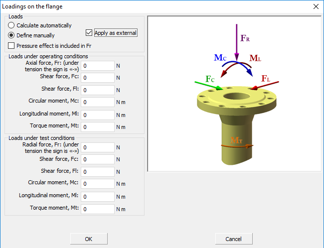
Fig. 14. Flange loads
Loads can be calculated automatically during analysis based on components
adjoining the flange joint or set manually. If  is selected, set loads on the flange joint will be transferred to all
model components.
is selected, set loads on the flange joint will be transferred to all
model components.