PASS/EQUIP → Working with PASS/EQUIP → Data input → Air cooled exchanger
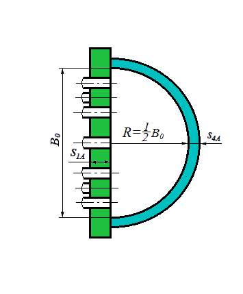
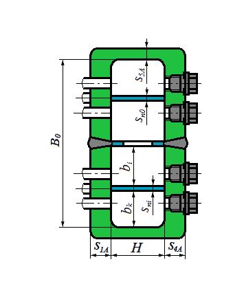
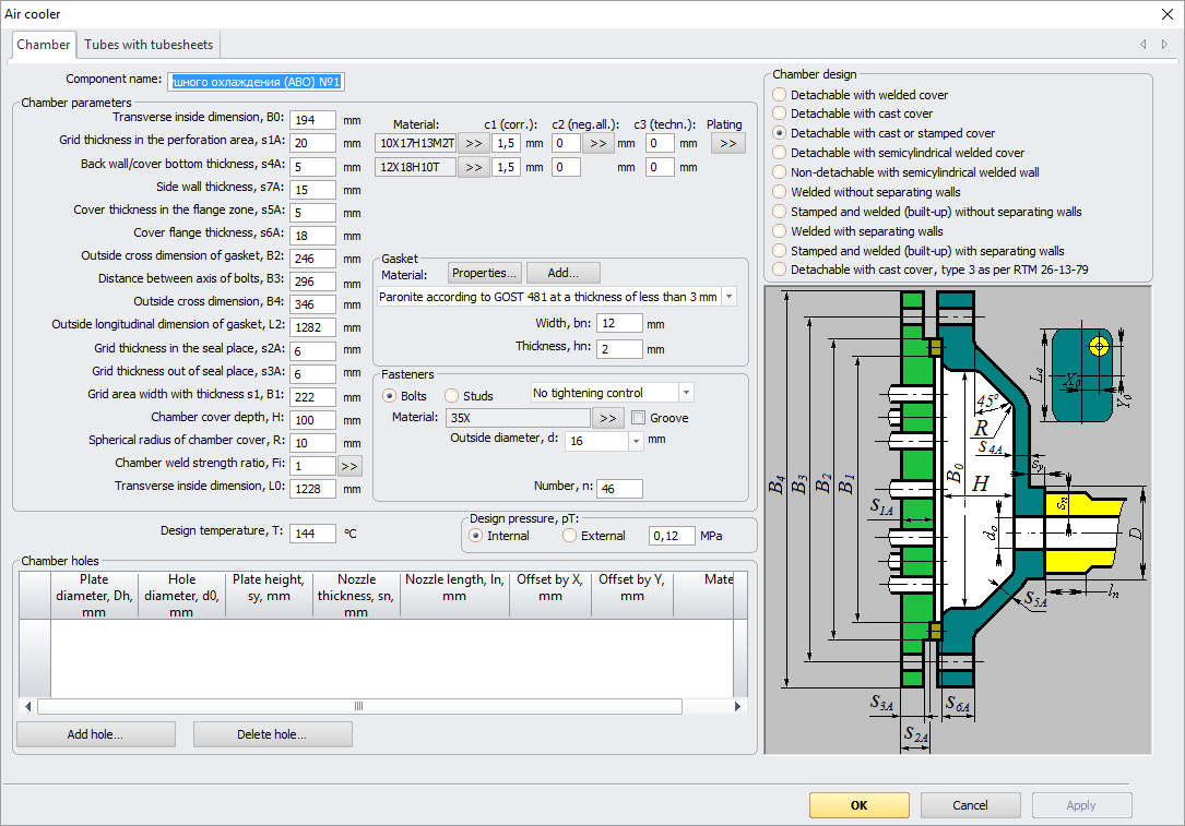
Fig. 1. Distribution chamber
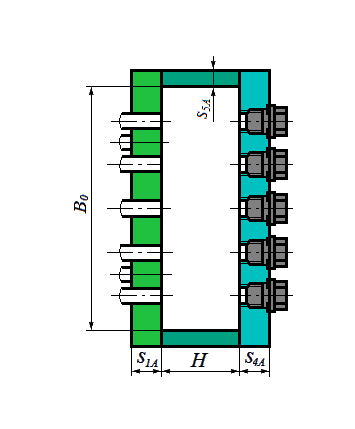
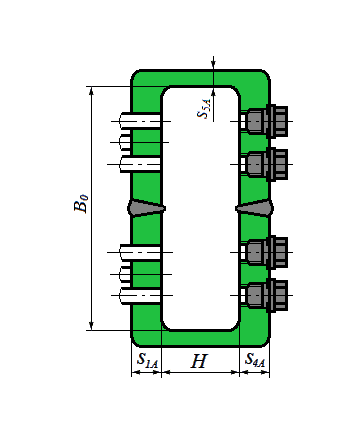
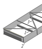
Air-cooled heat exchanger is created as a model component. This component cannot be joined to anything. No other components can be joined to it as well in the current program version. Air cooled exchanger consists of two identical distribution chambers (Fig. 2) and tube bundle (Fig. 3).
|
|
|
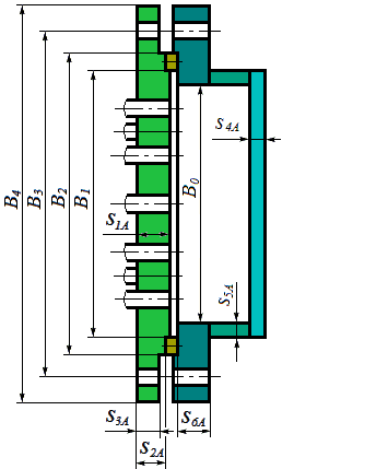
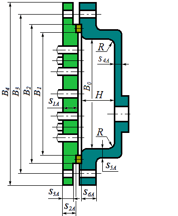
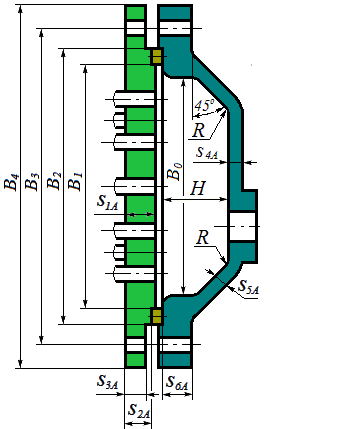
| Bolted with welded head | Bolted with cast head | Bolted with cast or stamped head |
|
|
|
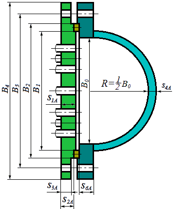
| Bolted with semicylindrical welded head | Welded with semicylindrical welded head | Welded without separating walls |
|
|
|
| Stamped and welded without separating walls | Welded with separating walls | Stamped and welded with separating walls |
Fig. 2. Types of distribution chambers
For welded components of heat exchanger, you can assign a negative tolerance, cladding.
|
|
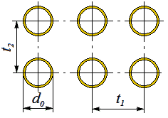
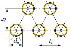
| Per tops of rectangles | Per tops of triangles |
Fig. 3. Types of tube bundles
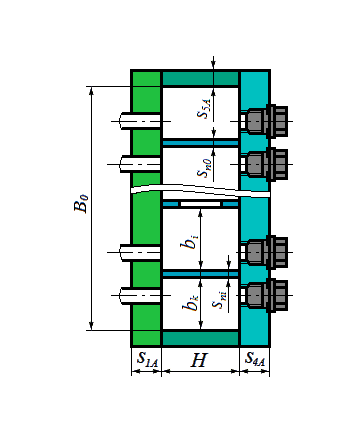
Upon pressing  button, tube bundle parameters
can be defined, similar to Heat Exchanger with
stationary tube plates.
button, tube bundle parameters
can be defined, similar to Heat Exchanger with
stationary tube plates.
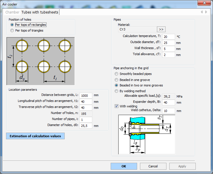
Fig. 4. Tube bundle
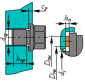
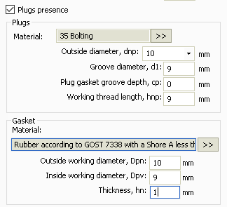
If there are screw plugs in the chambers (Fig. 5) they can be calculated according to PNAE G-7-002-86.
|
|
Fig. 5. Screw plugs in the chamber
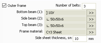
The outer frame can be set according to Fig. 6 (it is taken into account only in the visualization of the model and in the calculation of the metal consumption table)..
|
|
Р РёСЃ. 6. External air cooler frame