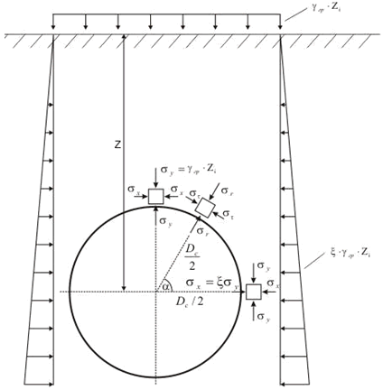

To calculate the ring bending stress the finite element model of pipe cross-section is used. The vertical and horizontal loads from soil weight are calculated and applied for each point of pipe cross-section at whole perimeter (see picture below).

Soil is modeled as discrete springs around pipe perimeter. The springs are working only for compression and each spring is switched off if tension is detected. The soil peeling usually take place at the top of the pipe cross-section (see picture below).
Also internal pressure and product hydrostatic pressure is applied acting in radial direction on each point of pipe perimeter. The analysis consider geometric nonlinearity, so the effect of additional resistance to the bending caused by internal pressure is also considered.

If open trench type laying is used, then chosen, then soil natural arch of collapse is not considered. The soil pressure on the pipe is calculated using whole depth. The soil pressure increases linearly with increasing depth.
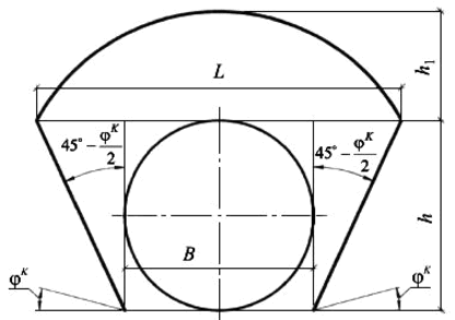
If trenchless laying method is used, and the pipe depth is very high, then a self-supporting arch collapse forms above the pipe (natural arch of collapse). This arch supports all the soil pressure above itself. Only soil inside the natural arch of collapse produce the pressure on the pipe.


The ring bending stress diagram is shown on the picture above. This stress is used in several piping codes to consider additional stresses in the pipe from the soil weight.