Subscribe to our newsletter, follow us in social
networks to stay updated on the new versions, latest developments and
special offers:
Updates |
4.86 R4
|
4.86 R3, 10.11.2023
Improved the PCF import/export function Improved algorithms for increasing the iterations
convergency, added iteration types 6, 7, 8 Added import from HEXAGON
CAESAR II v13, improved model conversion Imroved StressISO
3D generator into AutoCAD. Added support of AutoCAD 2023 Added information about number of iterations
for each load case into Error and Warning window Added ability to select piping using frame on
all graphics adapters Added detailed information about iteration convergence
for each load case Increase stability, bug fixes, other minor improvements |
4.86 R2, 10.03.2023
|
4.86 R1, 14.12.2022
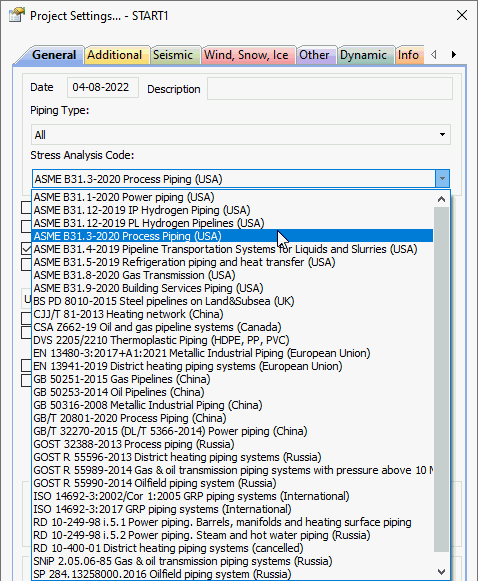
Updated pressure-temperature ratings for flanges
to the latest version ASME B16.5-2020 Updated standards in databases to the latest
versions: ASME B16.9-2018 (Bends, Tees, Reducers), ASME B36.19-2022,
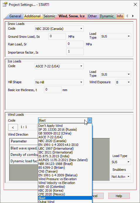
ASME B36.10-2022 (Pipes) Updated wind,
snow, and ice load codes to the latest versions: ASCE
7-22 (USA), IS.875.3.2015 (India), AS-NZS.1170.2:2021 (Australia/New
Zeland), NBC 2020 (Canada), CFE 2020 (Mexico), GB 50135-2019
(China), SP 20.13330.2016 addenda 3 Added Dubai wind
code 2013 Added Blast Load
(DNV RP D101) Added translation
into Spanish: whole user interface, Word reports
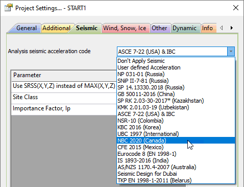
Added seismic
codes: ASCE 7-22 (USA), IBC, NSR-10 (Colombia), KBC 2016
(South Korea), UBC 1997, NBC 2020 (Canada), CFE 2015 (Mexico),
EUROCODE 8 EN 1998-1 (2013), TKP EN 1998-1-2011 (Belarus),
IS 1893:2016 (India), AS/NZS 1170.4-2007 Amendment 1,2 (Australia),
Seismic Code for Dubai 2013, SP 14.13330.2018 (Russia), GB
50011-2016 (China), SP RK 2.03-30-2017* (Kazakhstan), KMK
2.01.03-19 (Uzbekistan)
Added codes GOST 33962-2016, GOST 33964-2016,
GOST 33965-2016 Significantly improved the import
from CAESAR II function. Now it is much smarter and convert
much more details correctly
Fixed
test pressure conversion Added
ability to open cii files created using ISOTracer Added
uniform loads "U" and concentrated forces "F"
conversion Added
complex load cases conversion like "2W+2T1+1.2P1+1.3U1"-2.2U2+1.5F1 Added
flange class, material and code conversion Added
import of structural elements (beams)
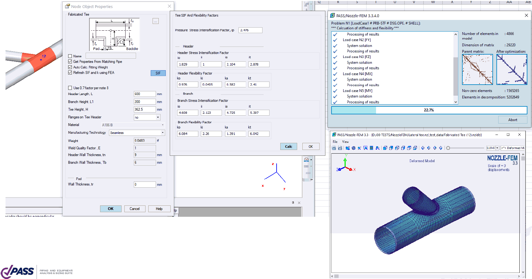
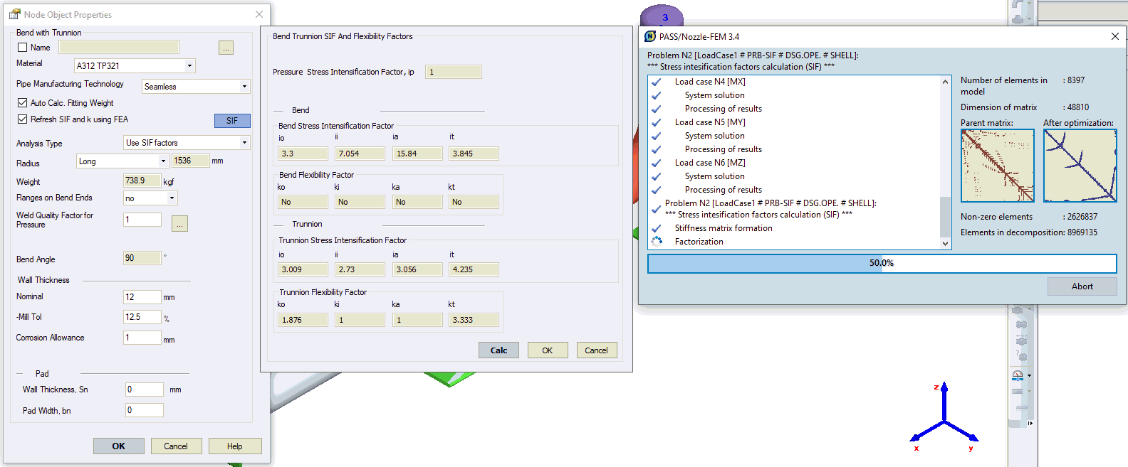
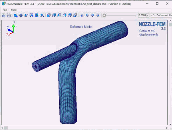
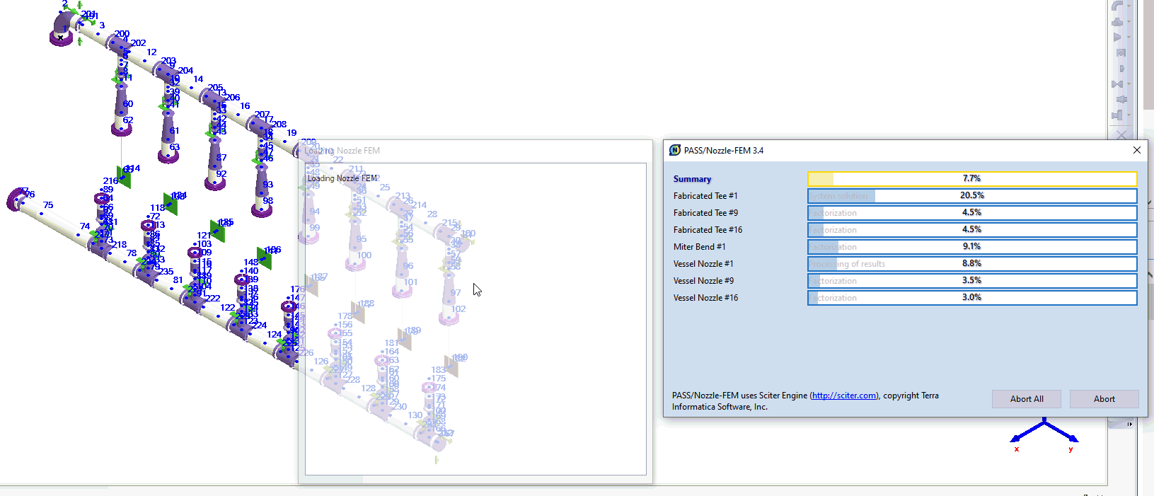
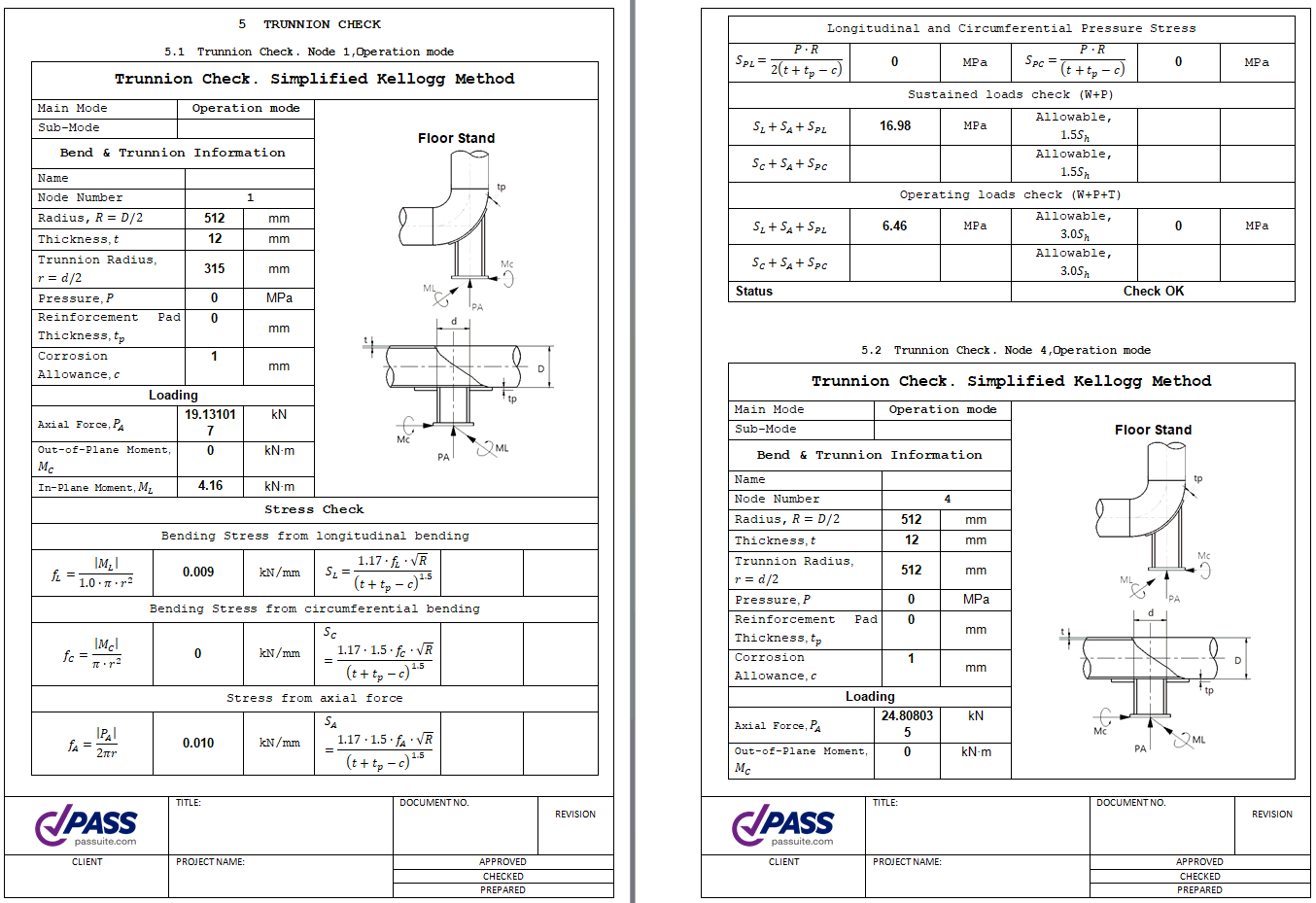
PASS/START-PROF
now directly integrated with PASS/NOZZLE-FEM
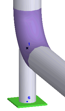
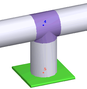
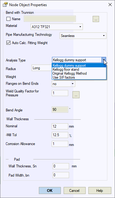
Software. Stress intensification factors for all tees,
bends, trunnions on the bend, trunnions on the pipe can be
automatically calculated using finite element method (FEA)
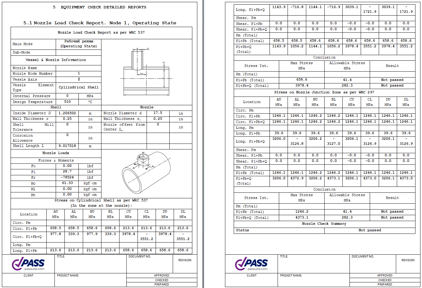
on-the-fly. Also vessel nozzle and tank nozzle stuffiness,
allowable loads and stresses can be calculated using FEA on-the-fly
automatically
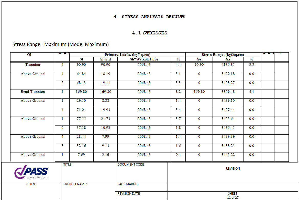
Added the
new MS Word report generator.
It has title page, contents, and generated automatically based
on the templates, that can be customized. You can insert logo
of your company, change font, layout, etc.
Added ability
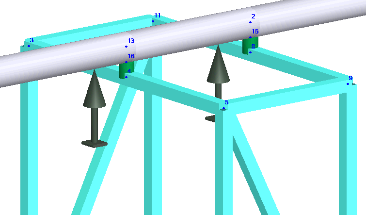
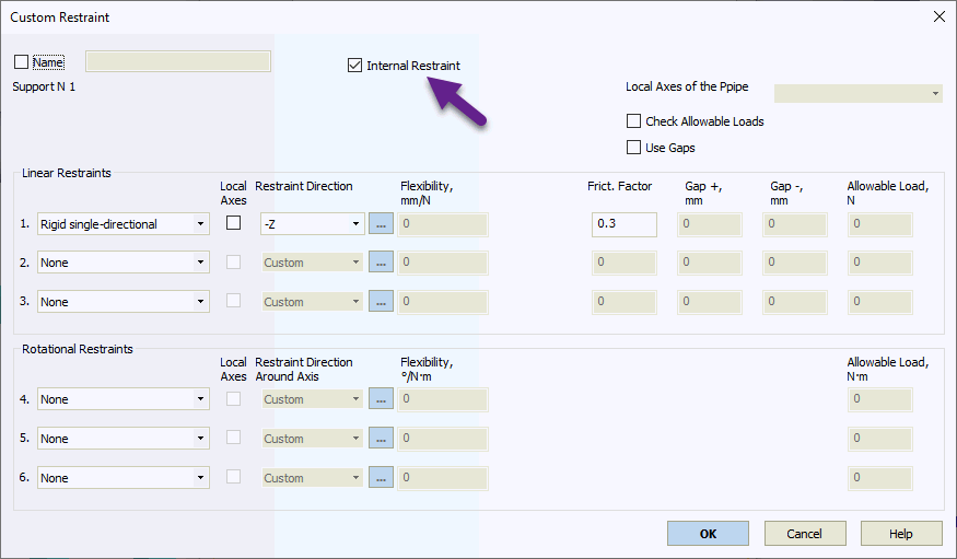
to model the internal restraints.
Internal restraint allows for example to model the resting
support which is connected to another pipe or beam element.
It allows to take into account the friction, single-directional
restraints, and gaps. Also it allows to model the pipe connection
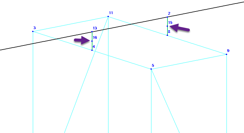
to column, and connection to skid, ramp, etc. Example. The pipe lies on the resting support,
that is connected to the frame made of I-beams. Between the
frame (node4) and pipe (node 13) we insert a rigid element.
On the rigid element at the distance of half pipe diameter
we insert a node 16. In this node we insert the internal restraint
that model resting support.
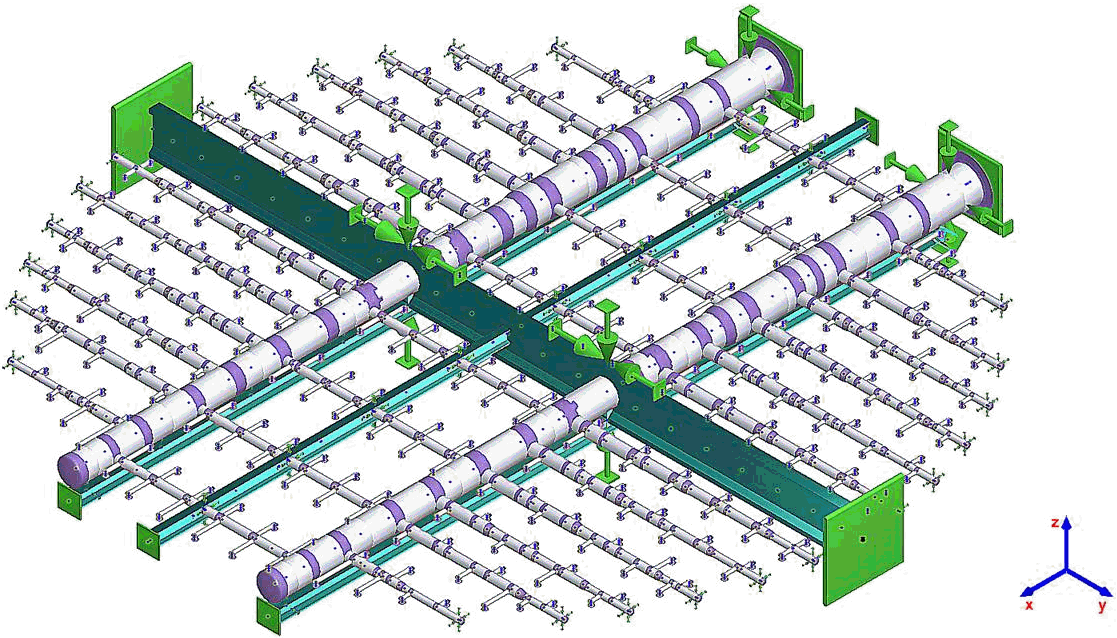
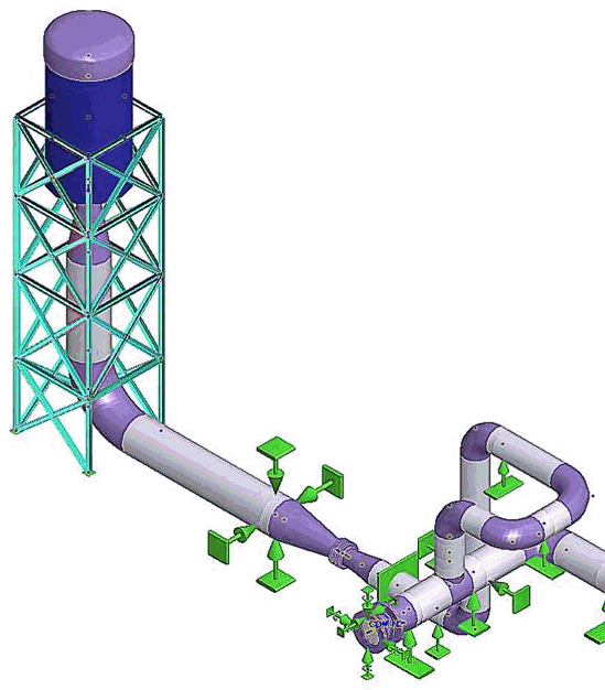
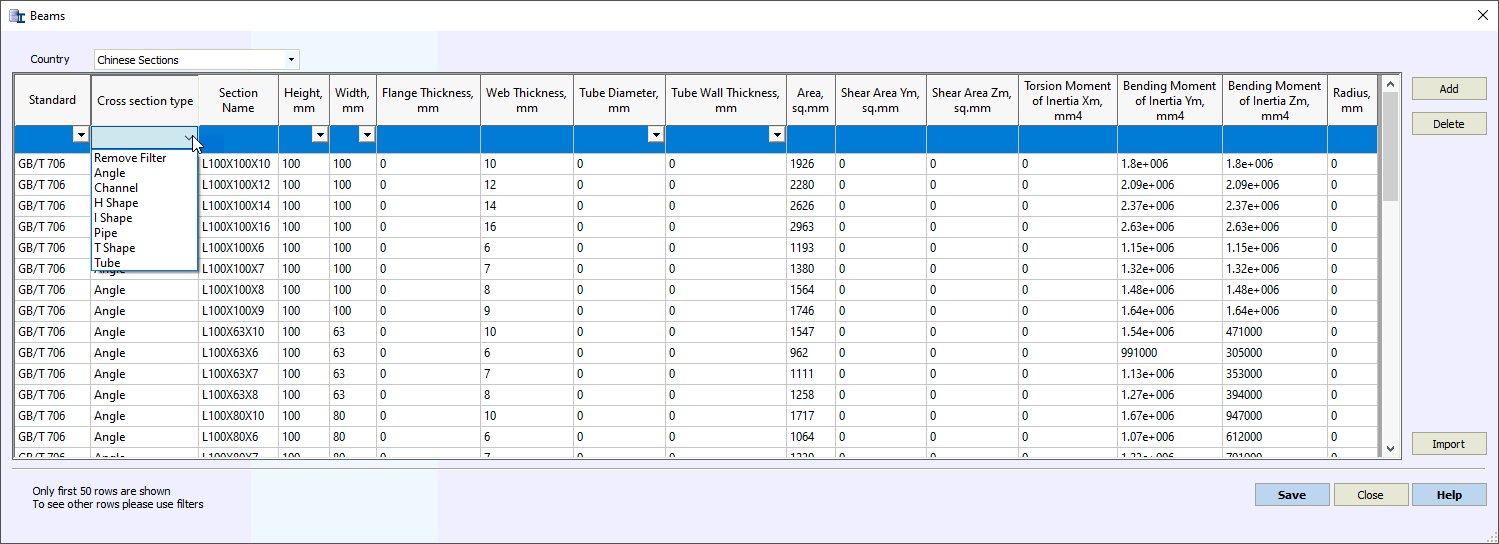
Added the
new object Beam, two-node element,
that allows to model the steel or concrete structure, working
in the same model with pipes. Beam elements can has different
sections: I-beam, Channel, Angle, etc. Profiles can be taken
from the beam section database
  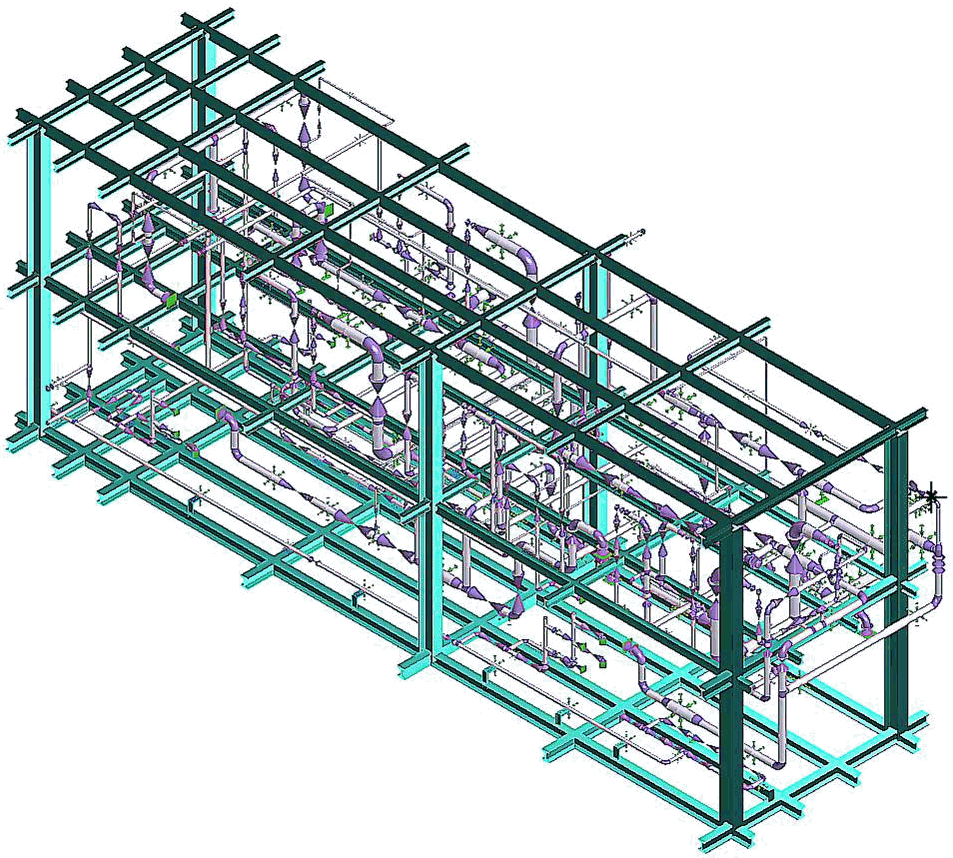
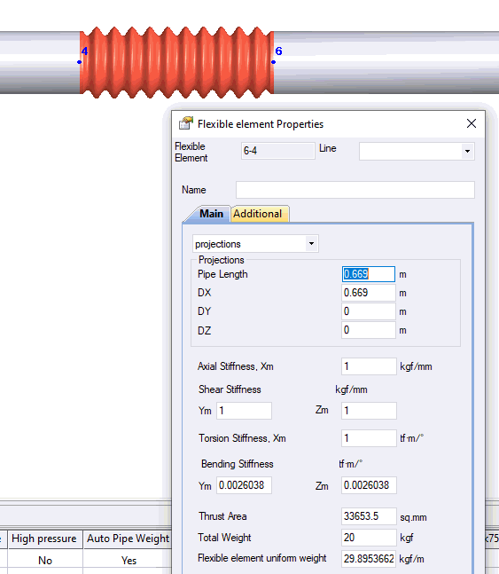
Added the
new object Cone, two-node element,
that allows to model the reducer. It is the same as reducer
object, but defined as two-node object
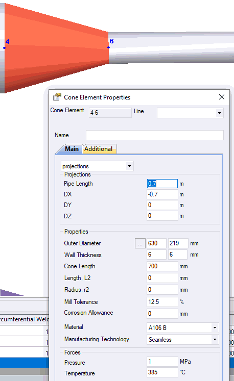
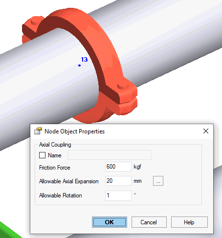
Increased
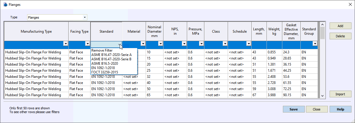
the speed of databases operation Added Flange Database and Single
Flange Database. Included into the flange database: ASME
B16.5-2020, ASME B16.47-2020 (Serie A, Serie B), EN 1092-1:2018,
GOST 33259
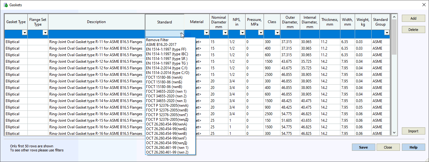
Added Gasket Database. Included into
the gasket database: ASME B16.20-2017, EN 1514-1, EN 1514-2,
GOST 15180, GOST 28759, GOST 52376, GOST 53561, OST 26.260.454,
OST 26.260.451, etc.
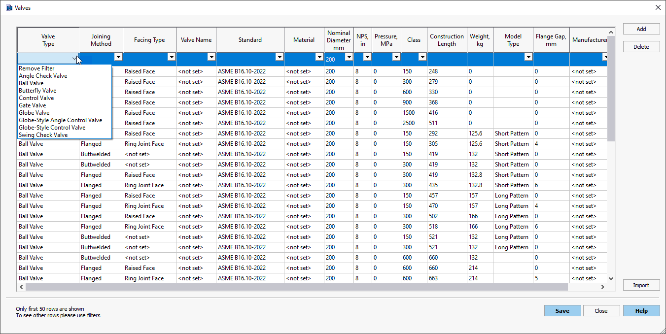
Added database
with material properties for beam elements Added the
latest catalogue data for expansion joints Belman, Witzenmann,
HKS Group, HTLY北京航天凌云 into expansion
joint database START-AVEVA
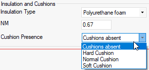
module: Added ability to import the bends with trunnions Added ability
to specify the type of expansion cushions for district heating
networks (soft, normal, hard)
Removed
restriction of intersection more than 3 pipe elements in the
node Added ability
to see the internal forces without the pressure thrust In the table
"Loads on the nozzles and equipment"
added ability to see the loads in the global coordinate system Added brand
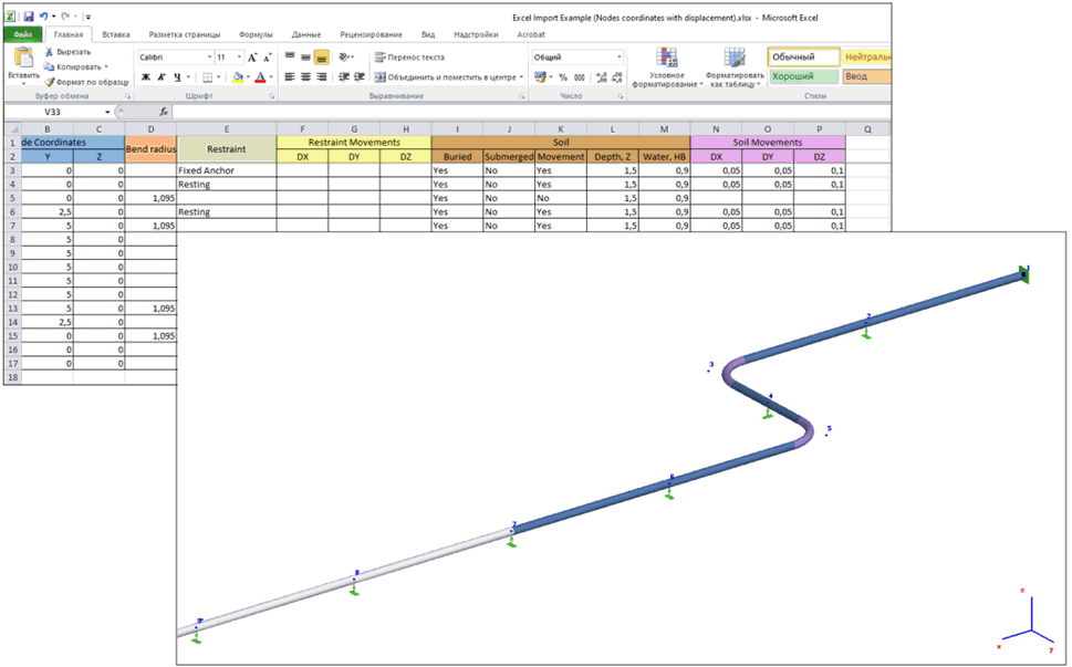
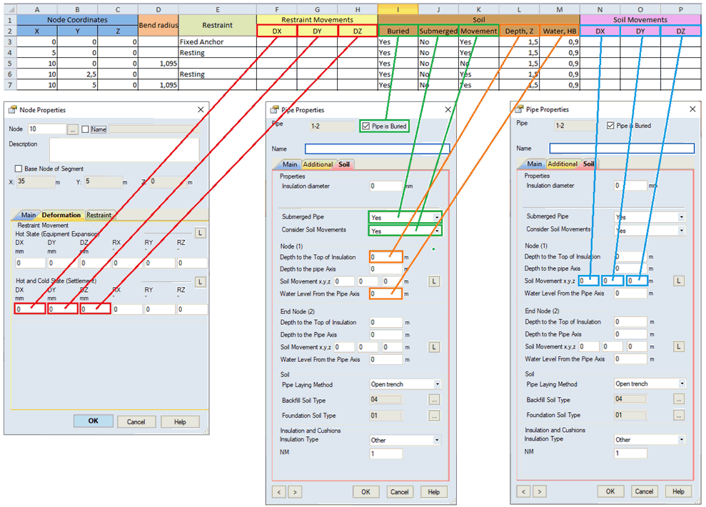
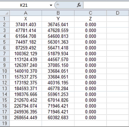
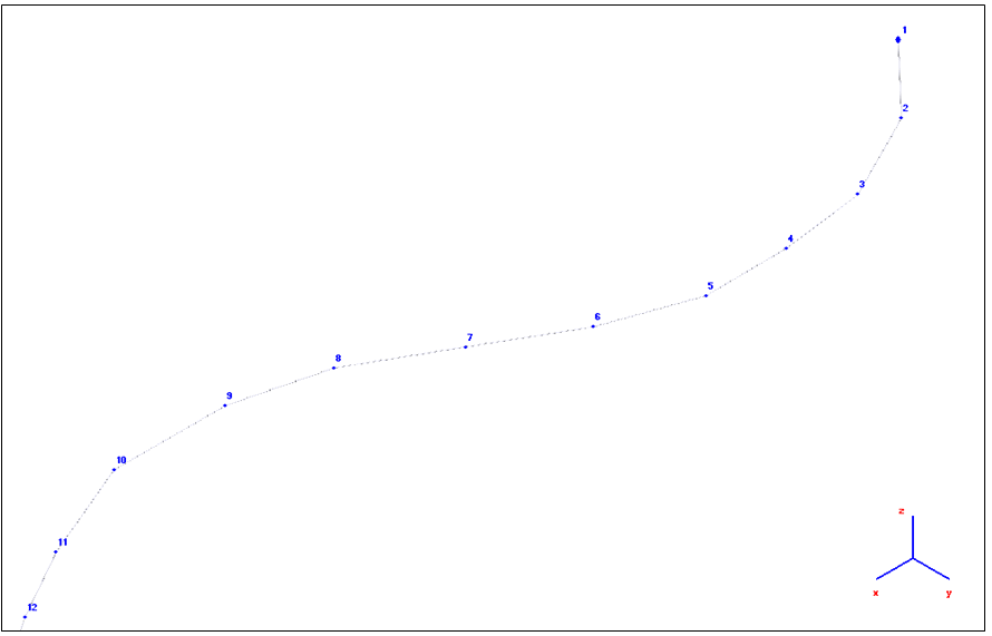
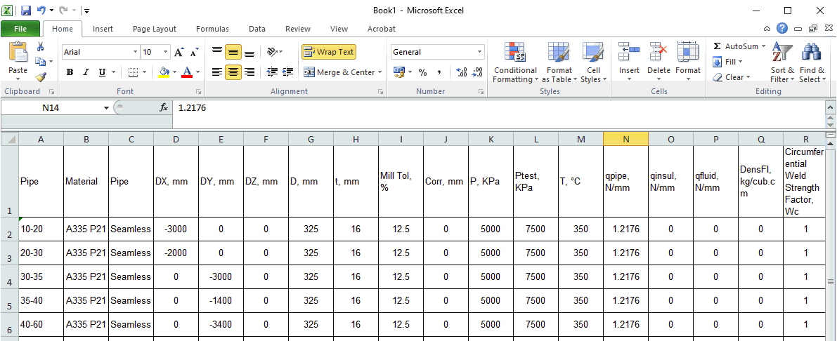
new import function from MS Excel.
The function allows to import pipeline geometry from an Excel
spreadsheet (".xls", ".xlsx", ".csv"),
created using one of several special templates
For the
floating window "Pipes List"
added ability to copy data into MS Excel and backward using
clipboard Added the
new floating window "Node List"
with ability to copy data into MS Excel and backward using
clipboard

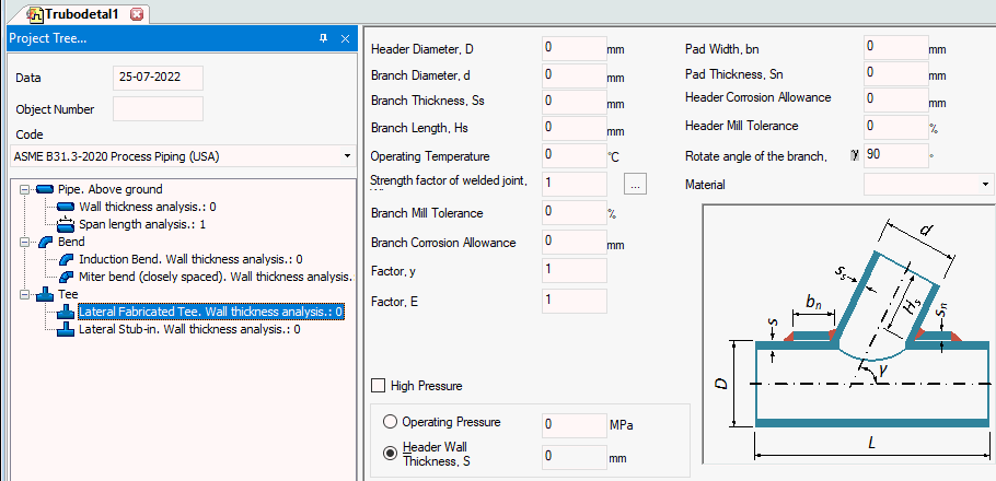
Added
tee wall thickness calculation
against pressure for ASME B31.1, ASME B31.3, ASME B31.4, ASME
B31.5, ASME B31.8, ASME B31.9, ASME B31.12, and some other
codes
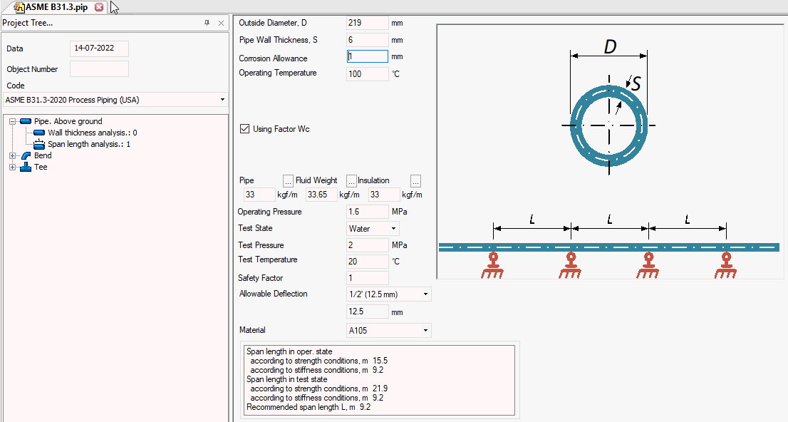
Added reducer,
cap, tee wall thickness calculation, pipe span calculation,
L-, Z-, U-shape loops analysis in START-Elements
per GB/T 20801 code Added import
from Autodesk Civil 3D Added export
into LICAD. In the LICAD v.11 added
function to import START-PROF spring data https://www.lisega.de/en/licad/
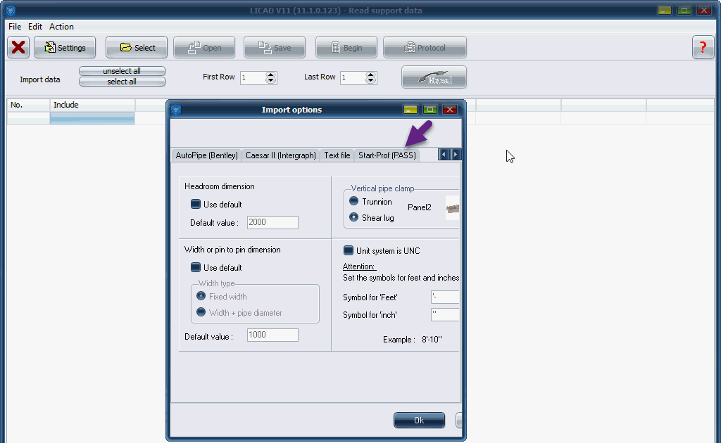
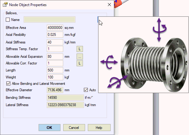
Added export of support loads into CSV file Added length
and weight properties for all types of expansion joints. he
same fields added into the expansion joint databases Added ability
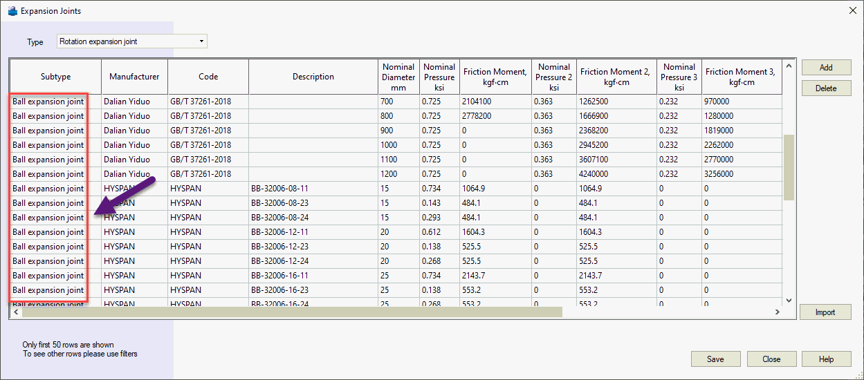
to specify stiffness or flexibility of expansion joints In the support
load table added the column with pipe diameter and summary
loads and moments (square root of squares by X,Y,Z) Improved
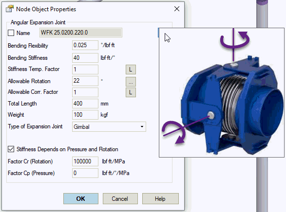
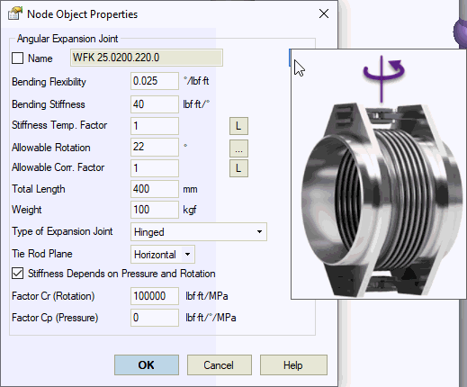
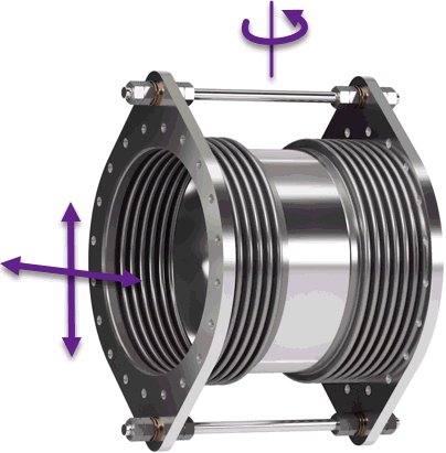
the Angular Expansion Joint model.
User can choose the type: gimbal or hinged. Added ability
to consider the effect of the temperature on the bellows stiffness
and allowable rotation angle. Added ability to consider the
pressure and friction effect on the expansion joint stiffness
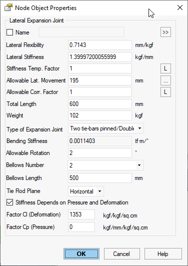
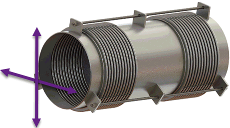
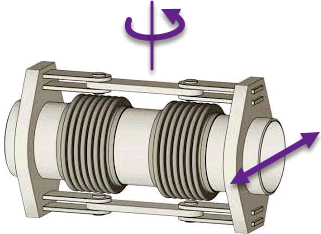
Improved
the Lateral Expansion Joint model.
User can choose the type: "Lateral three or more tie-bars",
"Lateral two tie-bars pinned (plane) expansion joint",
"Lateral two tie-bars spherical expansion joint".
Added ability to consider the effect of the temperature on
the bellows stiffness and allowable lateral deformation. Added
ability to consider the pressure and friction effect on the
expansion joint stiffness
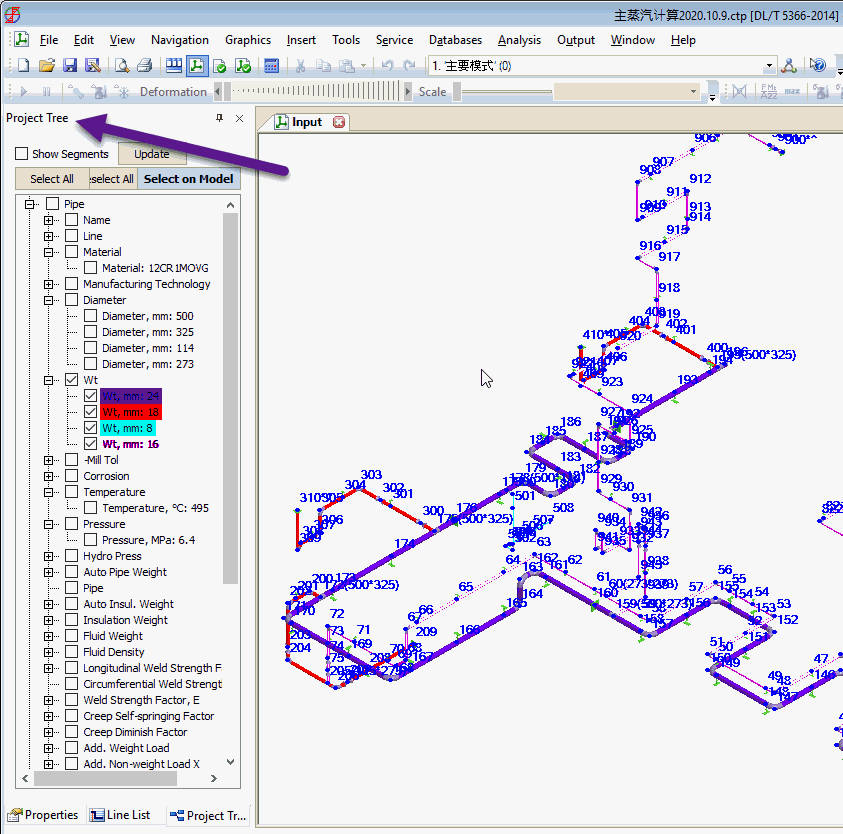
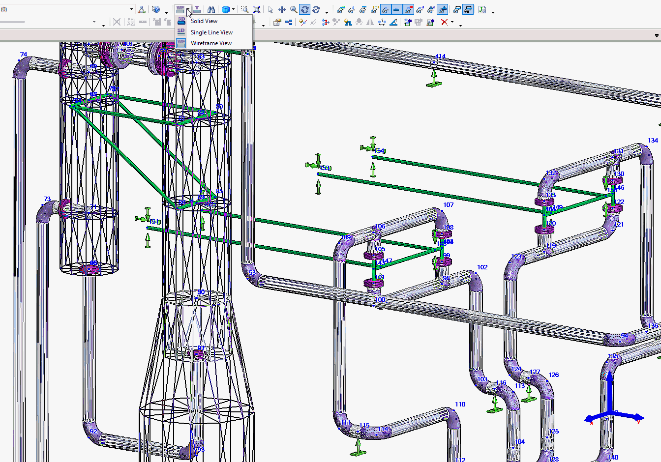
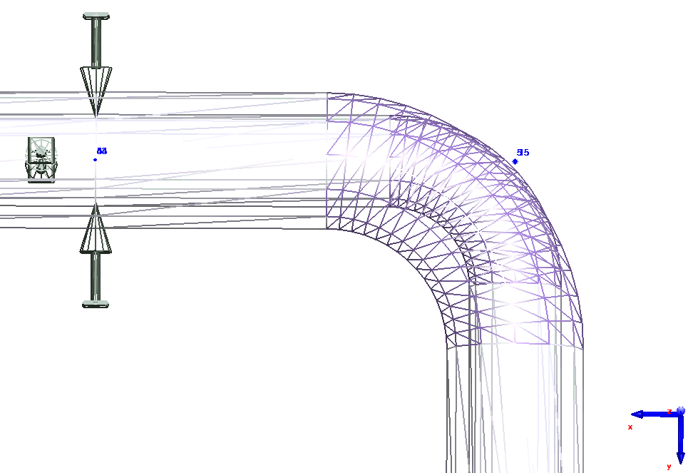
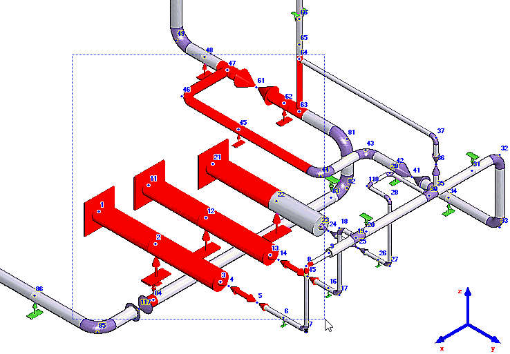
|
4.85 R6, 29.12.2021
|
4.85 R5, 30.09.2021

Significantly
improved the converter from CAESAR
II into PASS/START-PROF:
Improved of temperatures T, pressures
P, and support movements D from load case editor with
automatic recalculation for operation mode editor Added import of uniform loads U
and concentrated forces F from load case editor Added the zero length and finite
length expansion joints conversion with automatic recalculation
of flexibilities according to CAESAR II and START-PROF
rules Added conversion of restraints
that are non parallel to the axes X,Y,Z Added conversion of the most popular
CNODE techniques of application (support displacements,
nozzles, etc.) Added flange conversion with leakage
check parameters Added ability to drag-and-drop
CII files into START-PROF Changed the order of node numbering Improved units conversion Improved test pressure conversion Improved rigid element conversion Improved material conversion, spring
conversion Fixed a lot of other issues based
on 300 real CAESAR II (*.cii) models conversion sent us
by customers As the result, the 90% of imported
models now can be immediately analyzed without any issues
and error messages
Interface
with AVEVA (START-AVEVA) Improvements:
Added
option for import the trunnion accurate model Added
coordinates relative to the world Added
ability to import element name using parameter 449 Improved
user's guide Added
improvements suggested by users
Import
from PCF
Added
message if base node is not set Fixed
transfer of crotch height (parameter 24) Transfer
of bend through attribute TAG
Updated
code SP 20.13330.2016 addenda 3. Wind loads was changed Improved
HDPE piping analysis Fixed
bug with Witzenmann spring hanger selection Fixed
bug with tank nozzle load analysis per API 650 Fixed
bug with "Other pump" object Fixed
bugs in SP 284.1325800.2016 code Fixed
some problems reported by users |
4.85
R3, 27.04.2021
Added
ability to specify full weight for rigid element in addition
to uniform weight Added
ability to import load cases from
CAESAR II v.11, v.12 using Excel file Added
ability to import from CAESAR II 7.0 Added
new import from PCF function. In the
new function:
Ability to map attributes. You
can specify the START-PROF element corresponding with
the PCF attribute. Path to map files can be found in General Settings Ability to map materials. You
can specify the materials of START-PROF corresponding
with the PCF materials Ability to import the piping,
not connected with each other Ability to import the several
PCF files into one model Ability to import the group of
components FLANGE-GASKET-VALVE-GASKET-FLANGE as single
Valve element Ability to import the group of
components FLANGE-FLANGE as single Flange Pair element
Added ability to change the object
type property in project tree Updated code SP 284.1325800.2016 addenda
#1 Field pipelines Fixed some problems reported by users |
4.85
R2, 23.03.2021
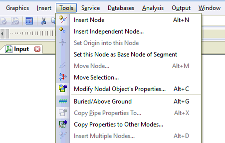
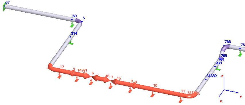
Added ability to insert the flange,
valve and joint element into the node on the edge of bend,
tee, valve, reducer, flange. Just insert
the node on the edge of the object and insert flange,
valve or joint into that node



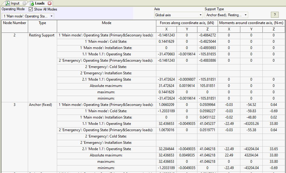
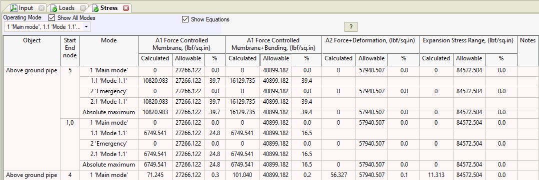
Added
the new representation of analysis results (support loads,
displacements, stresses, expansion joint deformations, etc.).
Now it is possible to see all load cases results simultaneously
in one table. You can choose which modes to see and print
to report

Improved converter from CAESAR II
for neutral format files created with FEATOOLS Added new iteration algorithms "Type
4" and "Type 5" Reduced the size of Word report. Removed
the repeated pipe properties from input table Fixed problem with export to DXF of
some files Fixed
load calculation in local coordinate system on intermediate
supports Fixed the problem with export to DXF Fixed other problems reported by users |
4.85 R1, 25.02.2021
Updated code ASME
B31.1-2020 Power Piping (USA) Updated
code GB/T 20801-2020 (China) Updated code SP 14.13330.2018 addenda
#1 Seismic analysis of structures Improved START-AVEVA Interface Significantly improved the import
from CAESAR II. Added support for CAESAR II v.8, v.9, v10,
v11, v12 Added ASME
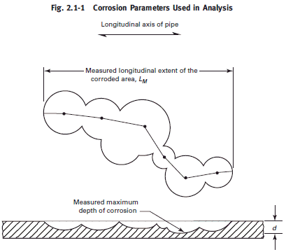
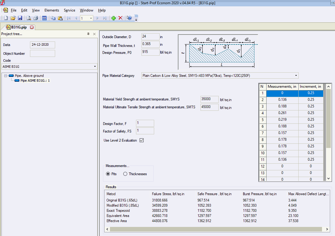
B31G-2012 Remaining Strength of Corroded Pipeline Analysis
Level 1 and level 2 in START-Elements: Original B31G (.67dL),
modified B31G (.85dL), Exact Trapezoid, Equivalent Area, Effective
Area
Added normal
modes analysis. The model is created the same way as for
static analysis, but need to activate option "dynamic",
after that the natural frequencies and mode shape animation
become available. The automatic mass discretization is implemented.
New analysis type is verified, added new examples into verification
manual.
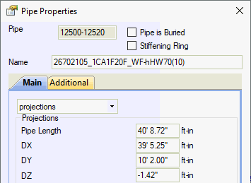
Updated
to the latest version ASME B36.19M-2018 code in pipe database Added
new parameters into concentric and eccentric reducer: full
length and cone angle Added
ability to edit the material database in any units Added
ability to insert the tank nozzle object
as intermediate object. In this case temperature expansions
and subsidence should be modeled manually using rigid elements.
It is needed to model several nozzles in the same tank Improved
EN 13941 expansion stress calculation Fixed
problems reported by users |
4.84
R4, 06.11.2020
Updated code ASME B31.5-2019 Refrigeration
Piping and Heat Transfer Components (USA) Updated
code ASME B31.12-2019 Hydrogen Piping and Pipelines (USA) Added
ability to import CAESAR II 2019 (v11) neutral files Added
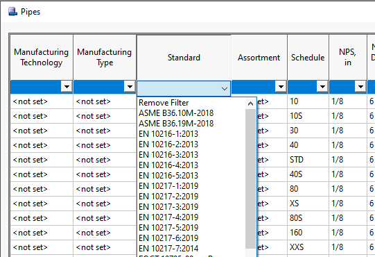
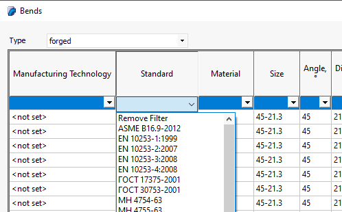
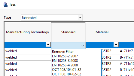
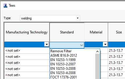
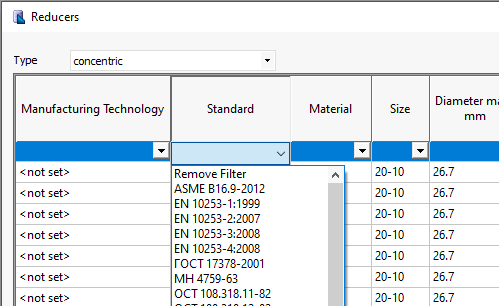
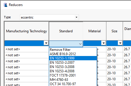
Pipes, Tees, Bends and Reducers properties according to the
EN codes: EN 10216-1:2013, EN 10216-2:2013, EN 10216-3:2013,
EN 10216-42013, EN 10216-5:2013, EN 10217-1:2019, EN 10217-2:2019,
EN 10217-3:2019, EN 10217-4:2019, EN 10217-5:2019, EN 10217-6:2019,
EN 10217-7:2019, EN 10253-1:1999, EN 10253-2:2007, EN 10253-3:2008,
EN 10253-4:2008
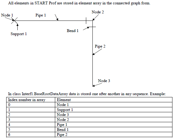
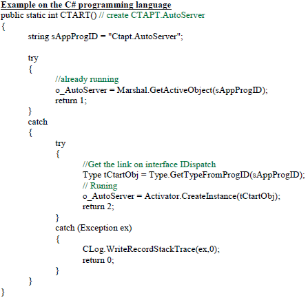
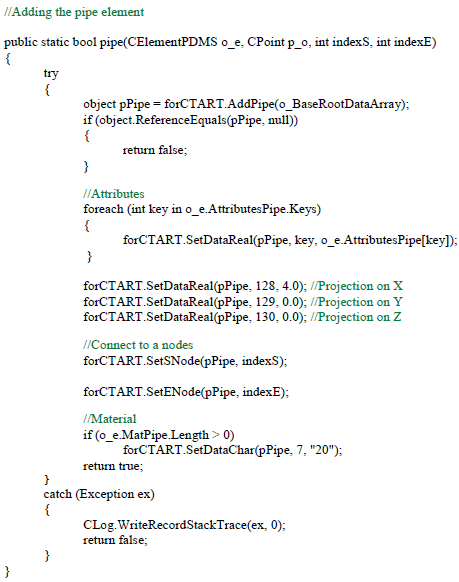
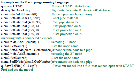
Added the short description of PASS/START-PROF API (application programming interface)
that allows for side applications on C#,
Basic and other programming
languages to create, modify and analyze models using START-PROF
and read the analysis results. It is used for creation of
plug-ins for START-PROF software. Full description available
upon request. How could it be used?
For example, the following plugins
was written using the PASS/START-PROF API: Export
to PCF, Import
from PCF, Export
to CAESAR II, Import
from CAESAR II, Import
from PDMS, QA
(quality assurance) software, that automatically
analyze a lot of models and compare results with previous
versions. Any company can create an own
plugin for seamless integration of PASS/START-PROF software
into company’s workflow. It is possible to write a plugin
that will automatically invoke PASS/START-PROF stress
analysis from 3D modeling software in background and transfer
the analysis results back or generate the reports following
the corporate templates Also it allows creating a plugin
for data conversion between PASS/START-PROF and any other
software Furthermore, the plugin for piping
model optimization or running complex sequences of parametric
model piping stress analysis can be created
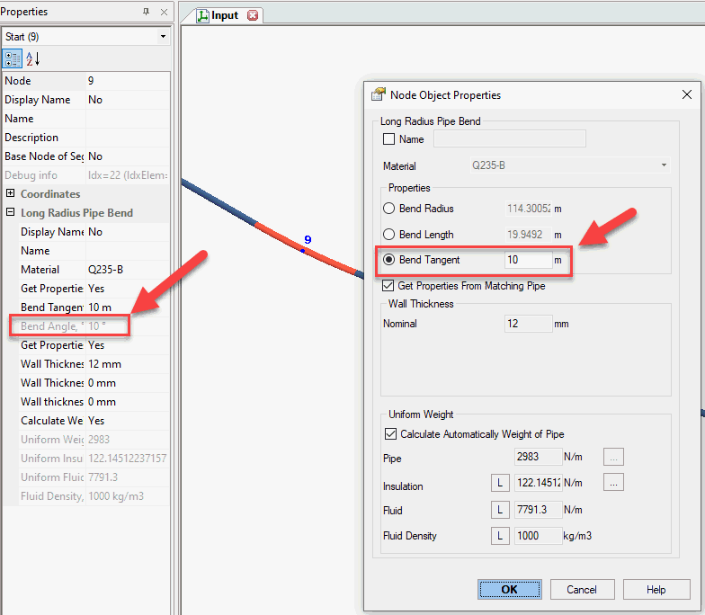
Added ability to put the miter joints
on the ends of the bend elements and other fittings Added
ability to set the turbine, compressor, pump,
and nozzle movements manually if
they are provided by manufacturer Added new codes SNiP III-42-80* and
SP 86.13330.2014 for construction stage of pipelines Pipe database
is updated with the latest version of ASME B36.19M-2018 EN
13941: Now using the effective axial
force instead of true axial force during stress calculation Removed restriction
to specify different pressures and temperatures on the pipes,
connected to the fittings (tees, bends, reducers). Now the
greatest temperature and greatest pressure are used for fittings
wall thickness check, SIF and k-factor calculation (if required
by specific code) Built-in calculator is added to the
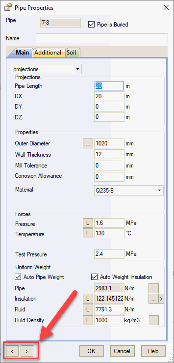
more fields of user interface Added ability
to switch between neighboring pipe objects without closing
the dialog
|
4.84
R3, 04.09.2020
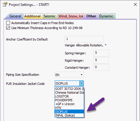
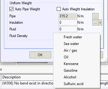
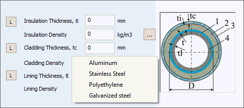
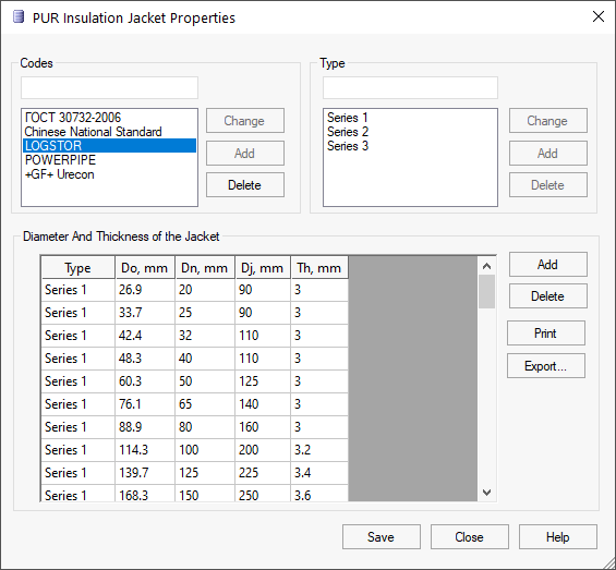
Added
ISOPLUS Polyurethane Pre-insulated Pipe Jacket Sizes Database
for district heating and district cooling network (Standard,
1x reinforced, 2x reinforced) Added
INPAL (Solice) Polyurethane Pre-insulated Pipe Jacket Sizes
Database for district heating and district cooling network
(Isolation Standard, Isolation +, Isolation ++)
Added
export to CAESAR II neutral file (.cii) Added
export to PCF (.pcf) file Added
ability to add the infinite number of nozzles to the turbine
and compressor objects Additional
force-based load values are now exported into MS WORD report
and in project tree Removed
hoop tangent stress check in insulation for the EN 13941 code Added
function to replace the flange with a rigid element Added
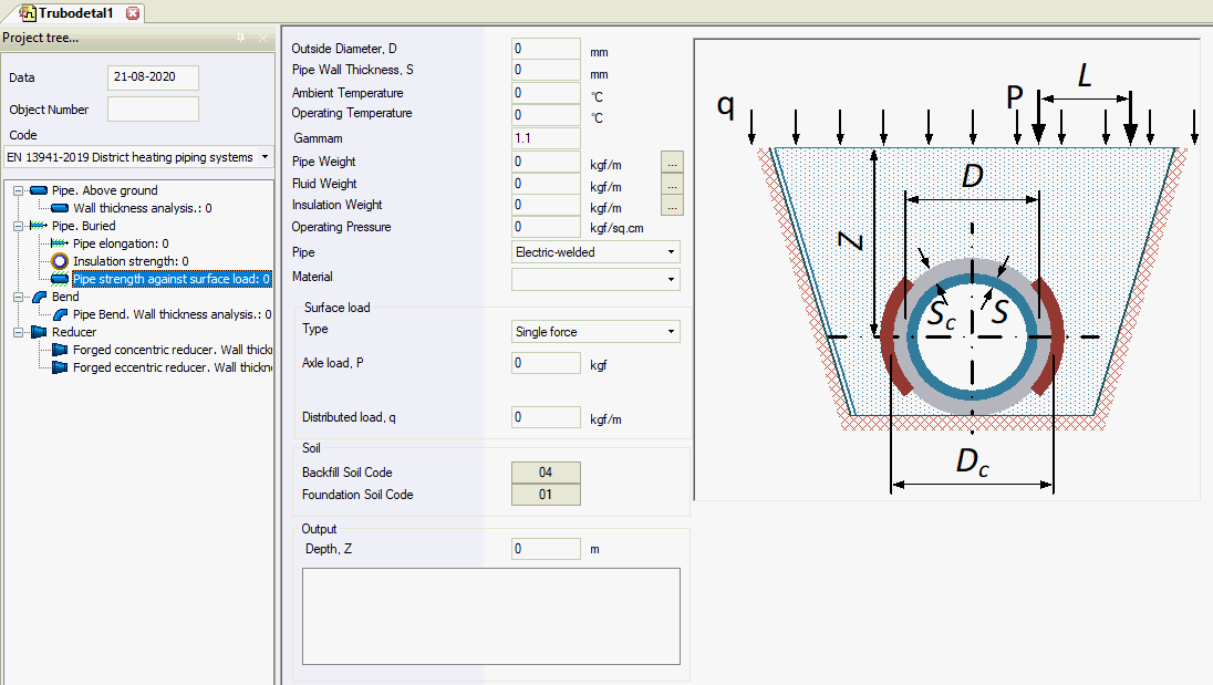
new analysis types for EN 13941 code
|
4.84 R2, 13.07.2020
Fixed
the file corruption during saving if hit twice the save button Added
function to copy the Pipe List
into clipboard. You can paste it into MS EXCEL Added
material PE 4710 to the thermoplastic database Improved
properties of PE-RT II material down to -30°C and up to 95°C Fixed
problems reported by users (20+) |
4.84 R1, 25.06.2020
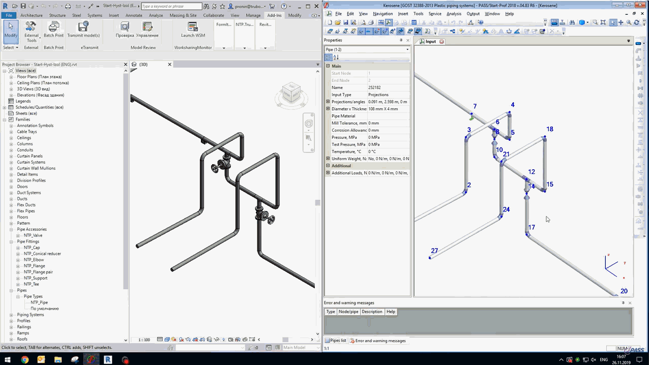
Updated
code ASME B31.9-2017 Building Services Piping (USA) Updated
code ASME B31.4-2019 Pipeline Transportation Systems for
Liquids and Slurries (USA) Added
new codes for pipe stress analysis.
See Full Supported Code List in current
version
ISO 14692-2017 Glass-reinforced
Plastics Piping (GRP) ASME
B31.12-2014 Hydrogen Piping and Pipelines (USA) BS PD 8010-1:2015 Pipeline
systems – Part 1: Steel pipelines on land (UK) BS
PD 8010-2:2015 Pipeline systems – Part 2: Subsea pipelines
(UK) CSA Z662-19 + Ch.11 Oil
and gas pipeline systems (Canada) GOST R 55989-2014 Gas and
Oil Transmission Pipelines for Pressure Greater 10
MPa (Russia) GOST R 55990-2014
Field pipelines (Russia) SP 284.1325800.2016
Field pipelines (Russia) SP 33.13330.2012 Steel
Pipelines (Russia) EN 13941-2019 District heating
pipes - Design and installation of thermal insulated
bonded single and twin pipe systems for directly buried
hot water networks (EU). START-PROF is widely used
for buried district heating network analysis since
1998 in Russia, since 2015 in China, and now available
for EU companies EN
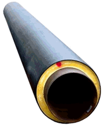
13941 7.3.1, 7.3.2, EN 253 added support for Polyurethane
foam insulation stress analysis using EN codes.
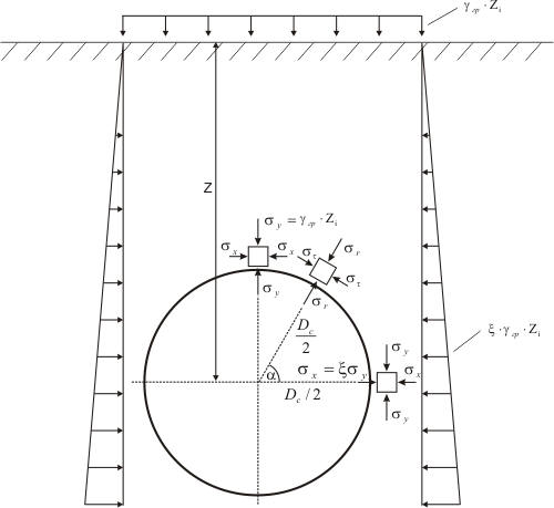
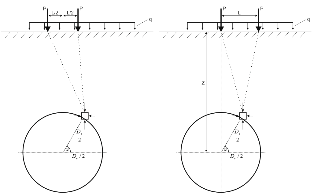
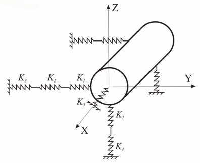
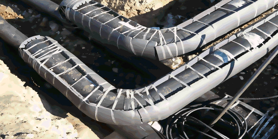
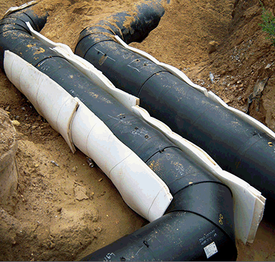
START-PROF can automatically perform analysis district
heating networks with single
use compensators or pre-heating,
pipe stress under surface
vehicle loads, take into account the stiffness
of polyurethane insulation and expansion cushions
Added
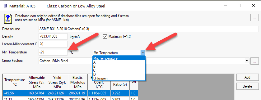
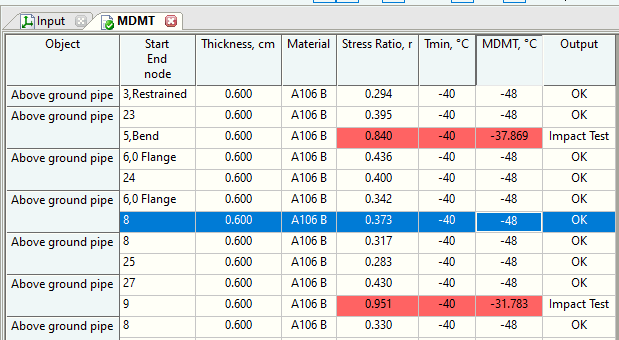
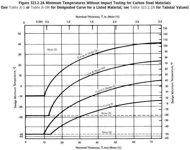
Minimum Design Metal Temperature (MDMT)
calculation according to 323.2.2 (a), (b), (d), (e), (f),
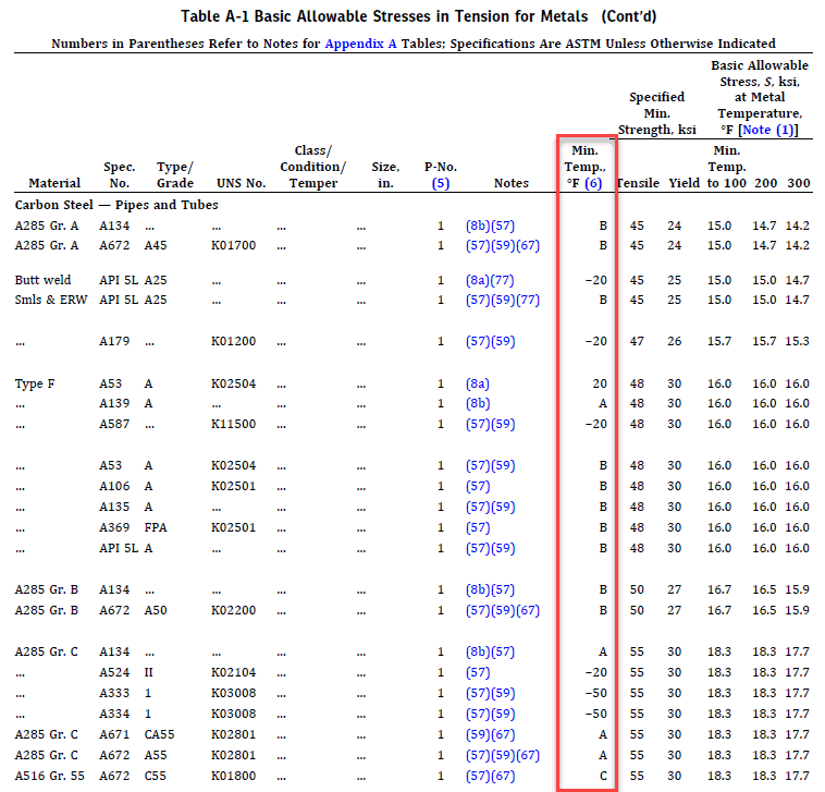
(g), (h), (i), (j) of ASME B31.3-2018. Minimum design
temperature values or curve A, B, C, D added fro all materials
in START-PROF ASME B31.3 material
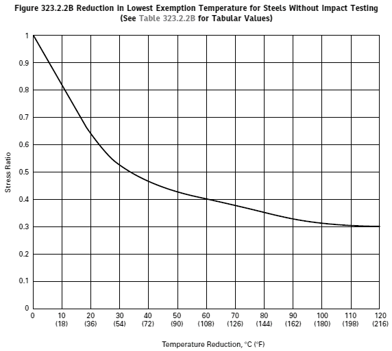
database. START-PROF automatically calculates the
MDMT according to minimum temperature from database or
figure 323.2.2A and automatically reduce it according
to figure 323.2.2B depending on the calculated stress
ratio if user select appropriate option in project settings,
taking into account the code requirements 323.2.2 (g),
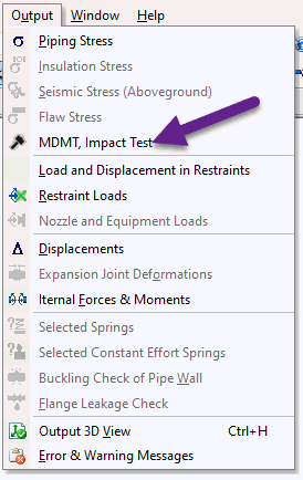
(h), (i). After analysis the output report table is provided.
For each pipe START-PROF show if the impact test is needed
or not
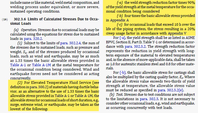
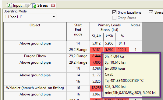
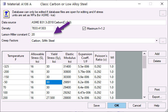
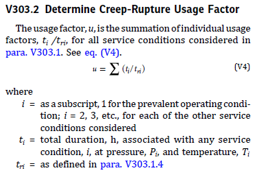
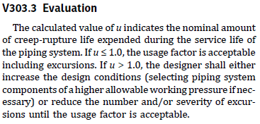
Updated
code ASME B31.3-2018. Updated material library, weld reduction
factors, modified occasional allowable calculation for
elevated temperature fluid service 302.3.6 (2), added
appendix V. Added "Time duration", "Alternative
Occasional" options to operating mode editor. Added
Larson-Miller constant "C" into ASME B31.3 material
database. For more information see code
stress table

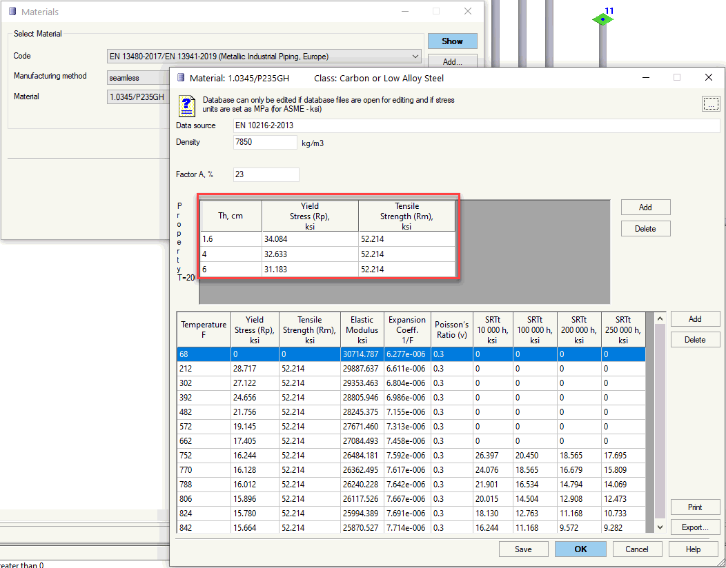
Updated material database
EN 13480/EN 13941. Added all piping materials by EN 10216-1-2013,
EN 10216-2-2013, EN 10216-3-2013, EN 10216-4-2013, EN
10216-5-2013, EN 10217-1-2019, EN 10217-1-2019, EN 10217-2-2019,
EN 10217-3-2019, EN 10217-4-2019, EN 10217-5-2019, EN
10217-6-2019, EN 10217-7-2014, EN 10220-2002 (2007), EN
10253-2-2007. Added automatic selection of material properties
depending on wall thickness and seamless/welding option
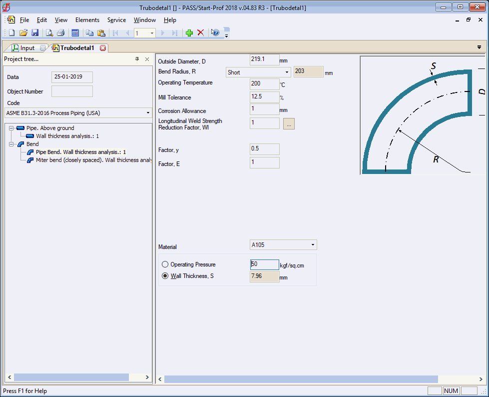
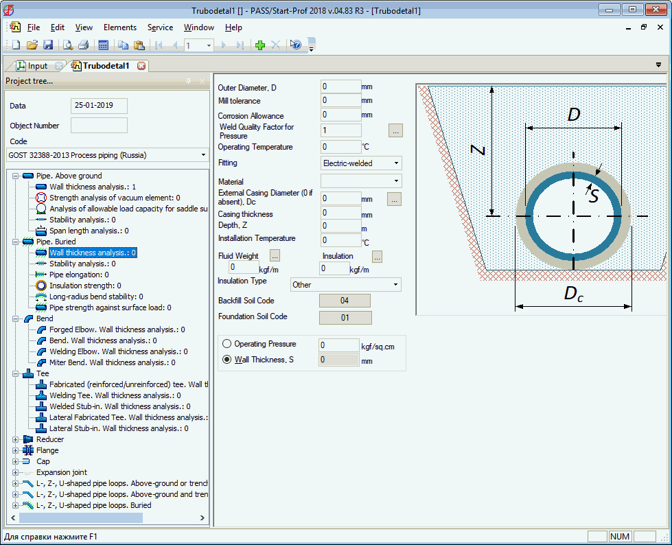
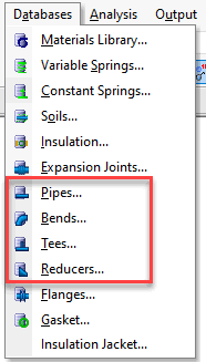
Added
pipe wall thickness calculator
and bend wall thickness calculator
for all new codes like ISO 14692-2017, EN 13941, ASME
B31.12, BS PD 8010, CSA Z662, GOST R 55989, GOST
R 55990, SP 284.1325800.2016, SP 33.13330.2012. And of
course, all pipes and fitting wall thicknesses are automatically
checked before every run of the pipe stress analysis according
to the selected code
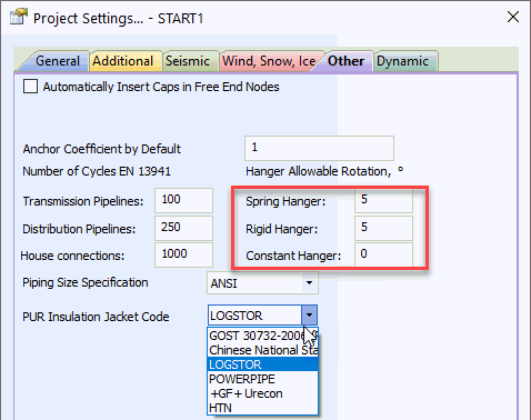
Now
it is allowed to add expansion cushions on the vertical
pipes. It was requested by the lot of our district heating
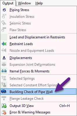
users Added
automatic local pipe wall buckling
check per ASME B31.8-2018 833.10 and EN 13941-2019
7.2.4.2
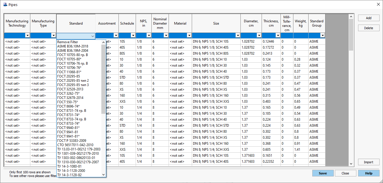
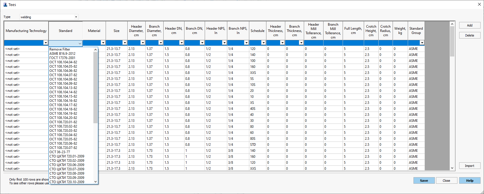
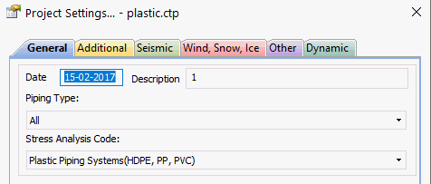 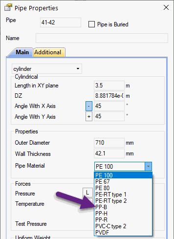
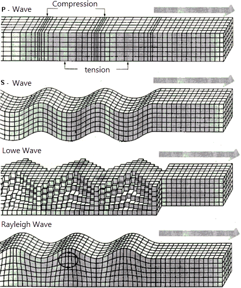 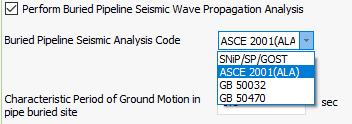 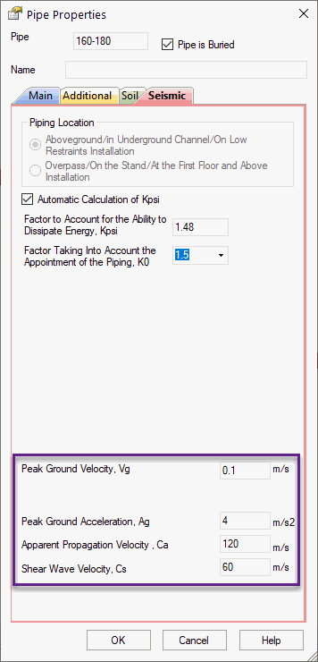


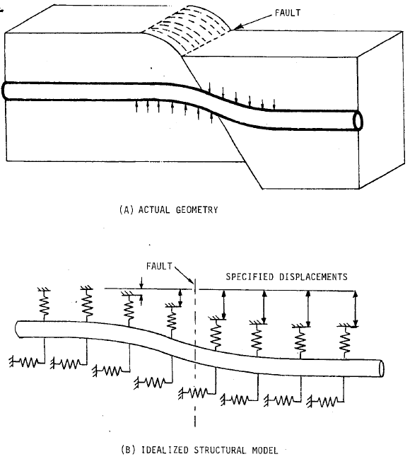
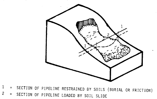
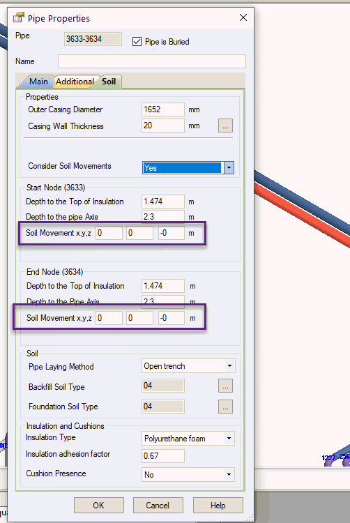
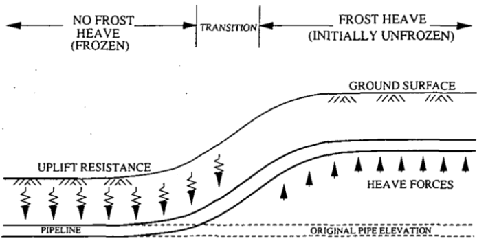
Landslide,
Soil subsidence, frost heaving, Permanent ground deformation
(seismic fault crossing)
can also be modeled. The pipeline
strain check is made according to ASCE 2001 (ALA) and GB 50470



Added ability to specify
different seismic anchor movement
values for the same phase group. It is used to define
various restraint movement on several floors of the same
building Added new functions to
Operation Mode Editor:
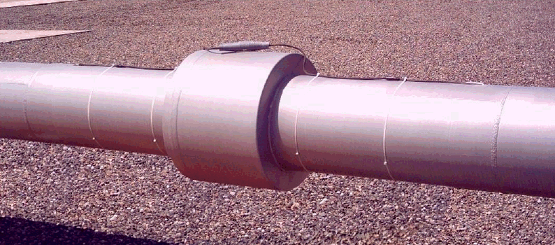
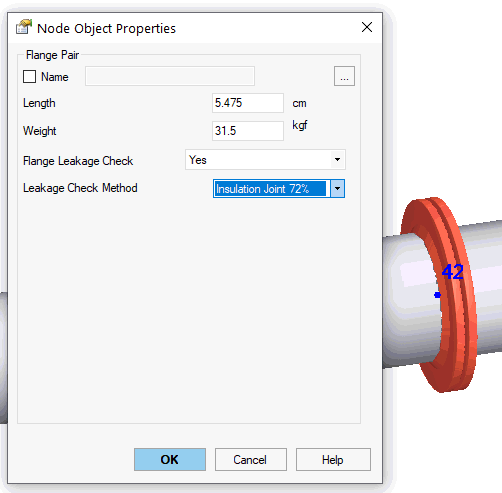
Disable overload factors, add a factor to weight loads Added Insulation Joint
(Insulation Kit) stress analysis. The axial stress and
stress from torsion moment is checked automatically
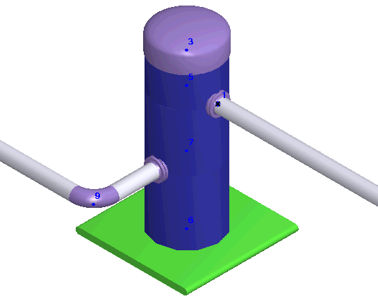
Added new object "Cylindrical Shell", that is
used for modelling of boilers,
pressure vessels, columns,
horizontal vessels,
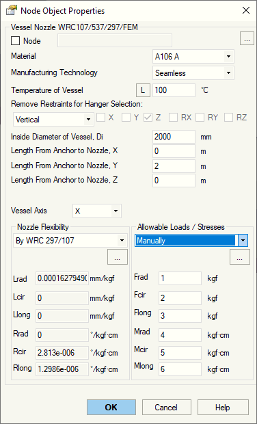
Added new object "Nozzle", allows to automatically
model nozzles of boiler and pressure vessels, and columns.
Automatically model shell flexibilities using WRC
297/PD 5500, custom values or FEM method, movements
due to thermal expansion of the vessel, checks allowable
loads, automatically checks stresses using WRC
107/537/297
  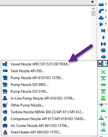
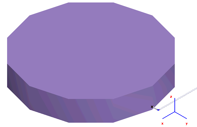
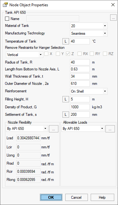
Added new object "Tank Nozzle API 650", allows
to automatically model the storage tank nozzles. Automatically
model flexibilities using API 650, thermal movements of
the nozzle, movements and rotation due to tank bulging
effect using API 650, tank settlement, automatically checks
allowable loads using API 650 and STO-SA 03-002-2009
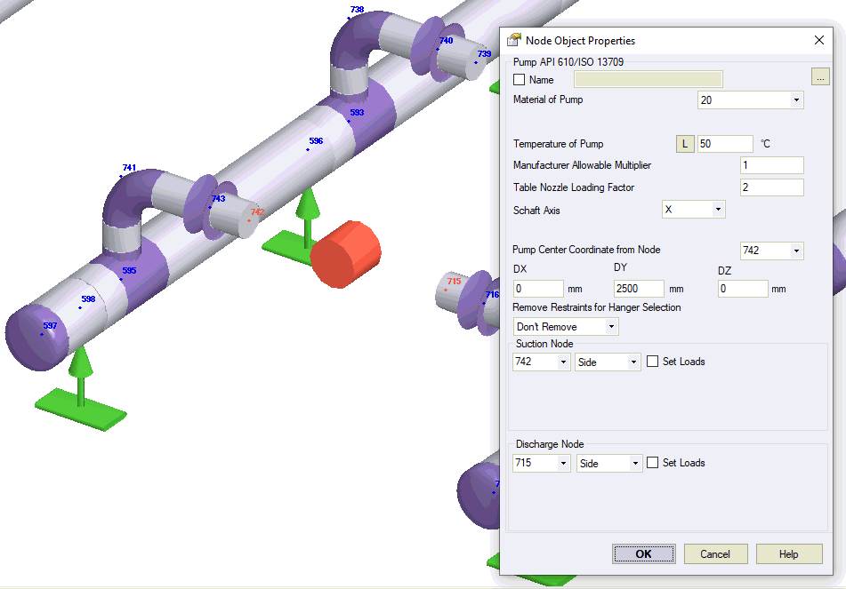
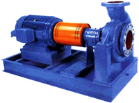
Added new object "Pump API 610/ISO 13709",
allows to automatically model the pumps, consider thermal
movements of the nozzles, checks allowable loads using
API 610 and ISO 13709
Added new object "Pump ISO 9905", allows
to automatically model the pumps, consider thermal movements
of the nozzles, checks allowable loads using ISO 9905 Added new object "Pump ISO 5199", allows
to automatically model the pumps, consider thermal movements
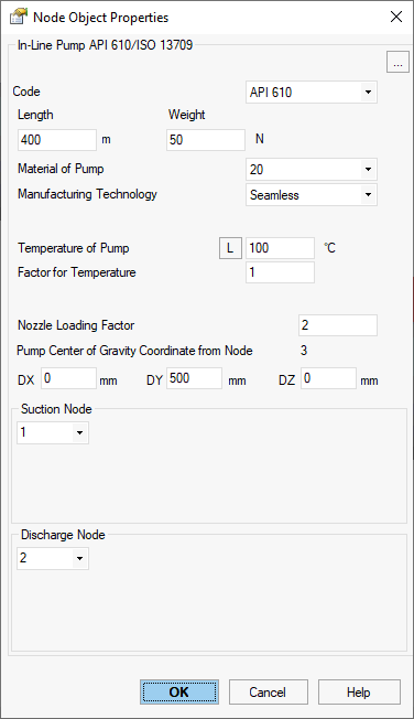
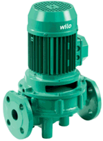
of the nozzles, checks allowable loads using ISO 5199 Added new object "In-line Pump", allows to
automatically model the vertical in-line pumps, consider
thermal movements of the nozzles, checks allowable loads
using API 610 and ISO 13709
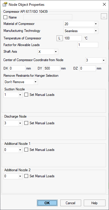
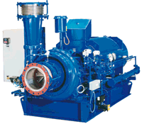
Added new object "Compressor API 617", allows
to automatically model the compressors, consider thermal
movements of the nozzles, checks allowable loads using
API 617 and ISO 10439
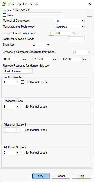
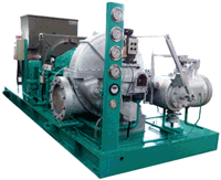
Added new object "Turbine NEMA SM23/API 611/API 612",
allows to automatically model the steam turbines, consider
thermal movements of the nozzles, checks allowable loads
using NEMA SM23, API 611, API 612, ISO 10437
Added new object "Other Pump", allows to automatically
model the pumps, consider thermal movements of the nozzles,
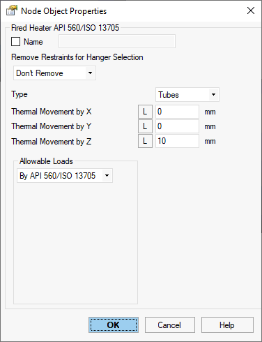
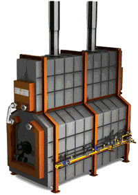
checks allowable loads Added new object "Fired Heater API 560/ISO 13705",
allows to automatically model the fired heaters, consider
thermal movements of the nozzles, checks allowable loads
using API 560 and ISO 13705
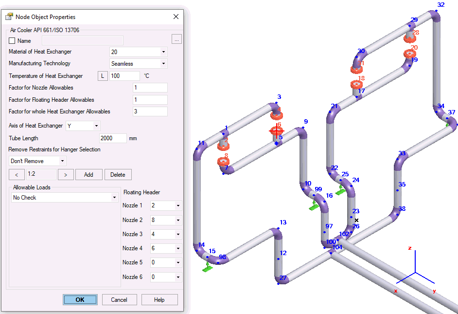
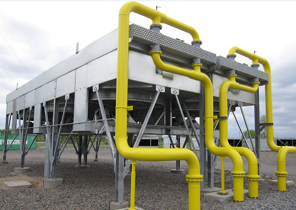
Added new object "Air cooled Heat Exchanger API 661/ISO
13706", allows to automatically model the air
cooled heat exchangers, consider thermal movements of
the nozzles, checks allowable loads using API 661 and
ISO 13706
  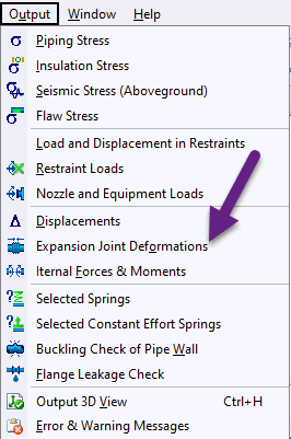
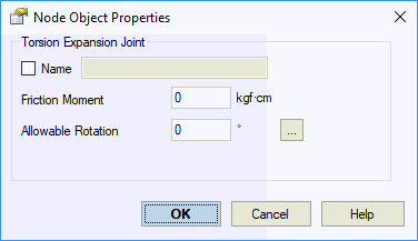
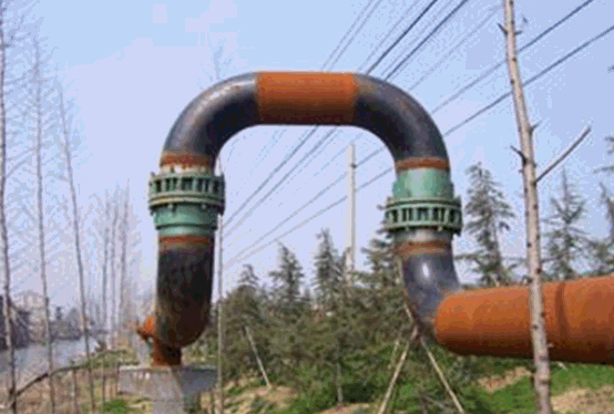 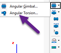
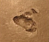 
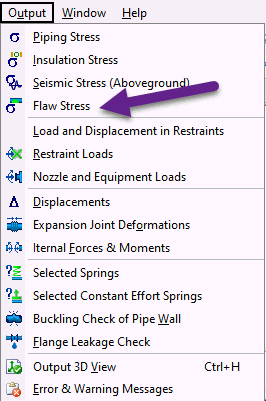 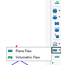
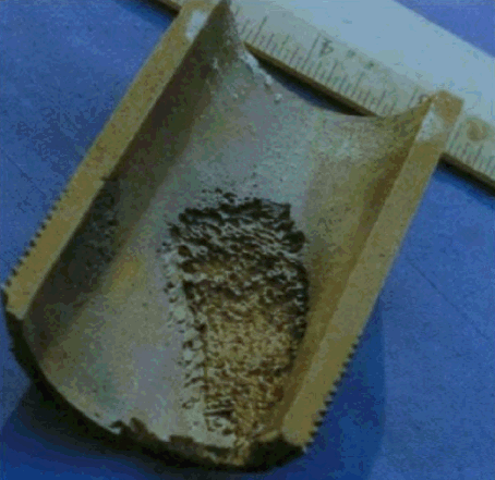
Added new object Volumetric
Flaw, allows to model the plain flaw on the pipe,
bend and tee elements, and check the stresses in the flaws

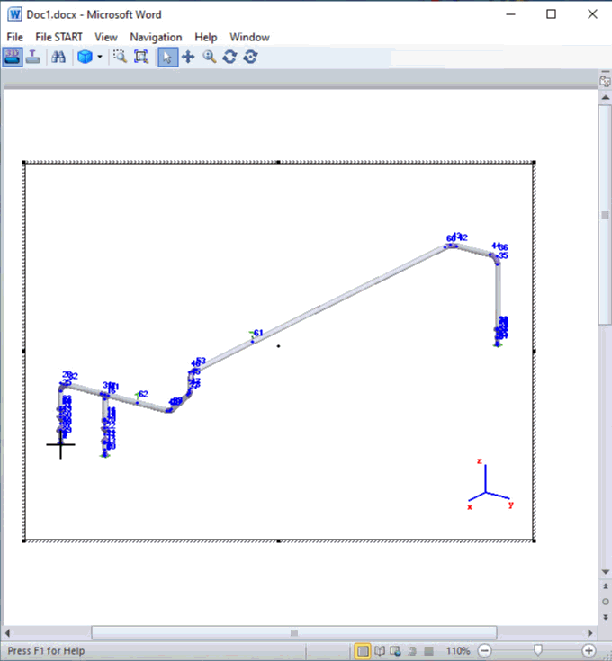
Added function "Copy Whole Model".
Allows to copy whole piping model as an object into clipboard.
After that you can insert this interactive model into
any other software like MS WORD, EXCEL etc. You can rotate,
pan zoom the model right inside MS WORD
Added
export to EHS pipe support sizing software. START-PROF
can create cad8.dat file Added
function that save backup copy of the file before each
run with date and time stamp. It is available in general
settings Fixed
lags while copying and cutting of pipes in the big piping
models Fixed
the rotation function for models, that consist of several
independent segments Added
automatic compression of START-PROF piping model files
(.ctp). Now files become 10 times smaller Significantly increased
the speed of opening and saving big piping models into
file Allows to insert the Joint
element into nodes between the pipe and Rigid
Element Added new topics into Application
Guide Created full Validation and
Verification report. Added a lot of verification examples,
compared to manual calculations, CAESAR II and other software In previous versions stress range was calculated
between operating state and cold state with multiplier
to friction forces 0.5. It was don by default for safety
reasons. In current version we decided to use full friction
factor for cold state that is used in calculating stress
range. If you need to get results the same as in previous
version, then create the second operating mode with friction
multiplier 0.5 and calculate stress range between operating
state and cold state with friction multiplier 0.5 Fixed
some minor bugs
|
4.83 R7, 24.12.2019
|
4.83 R6, 22.08.2019
|
4.83 R5, 18.06.2019
Added
function to import waterhammer loads from PASS/HYDROSYSTEM
software. See
video Added
function to import and export
support movements into text file (.csv) that can be modified
by Excel. It is used to model ship deck hog & sag, bridge
and other structure deformation Added
new wind load code CFE 2008 (Mexico)
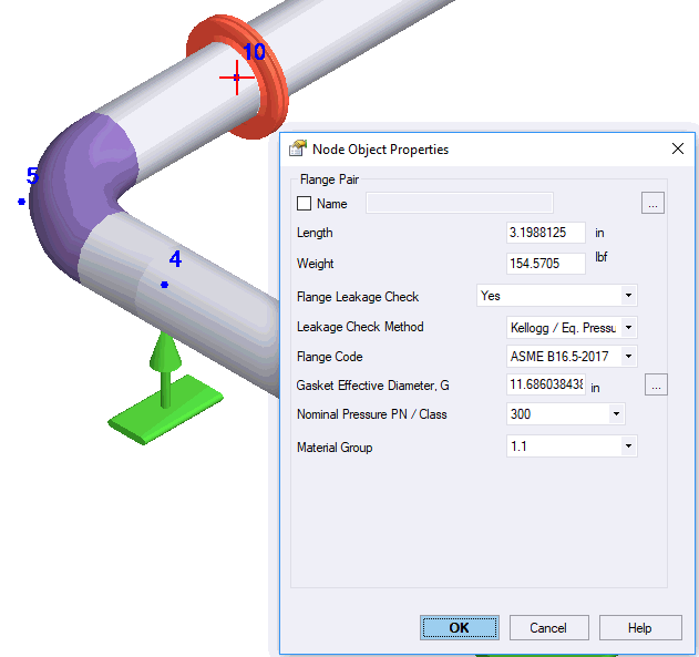 

CJJ/T 81-2013:
Added additional optional check by EN 13941 A2 criteria Removed
restriction for different loads (product weight, insulation
weight, additional weight, additional non-weight) on tee and
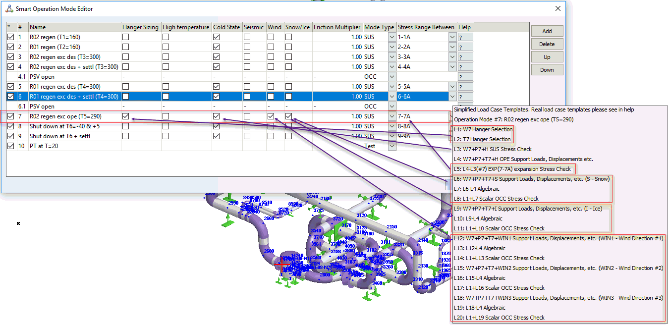
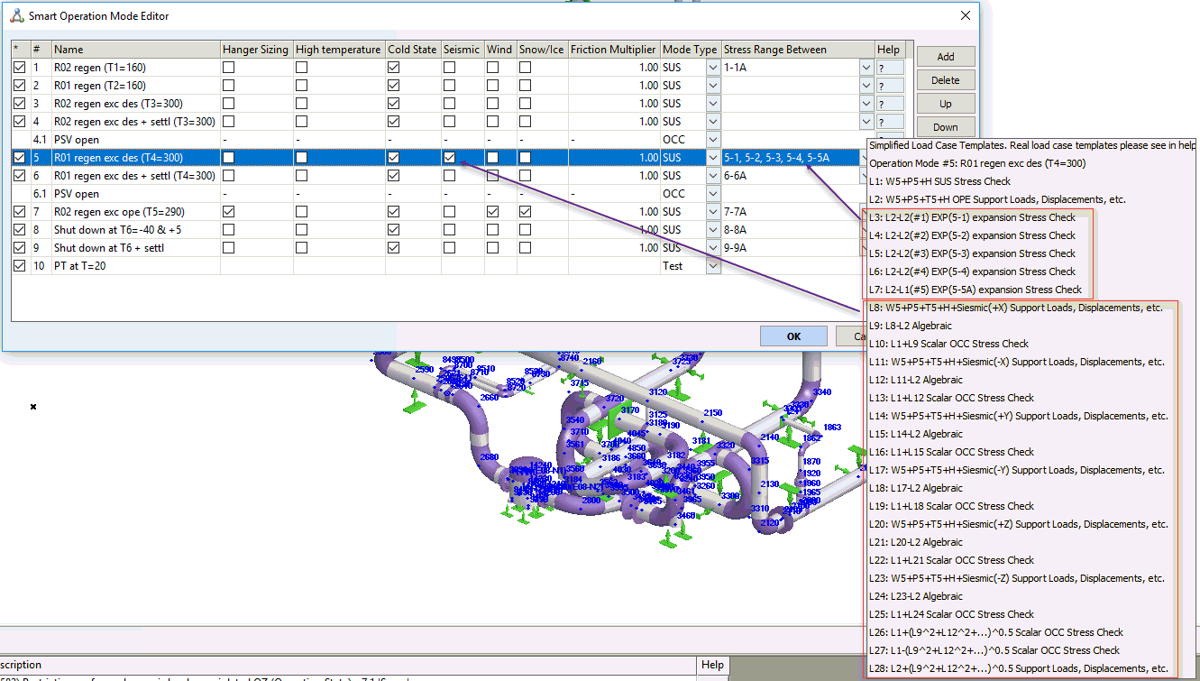
bends. Now average value of loads is taken for tee and bend Added
interactive tips with load cases explanation in operation
mode editor

Increased
analysis speed of some big models 2-5 times Increased
START-PROF application loading speed Increased
2-20 times the speed of opening of a big models Increased
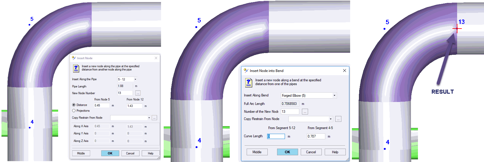
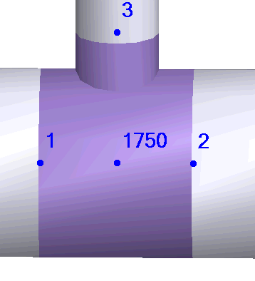
speed of project tree for big models Added
ability to insert the node right at the end of the bend, valve,
flange, tee using insert node
function
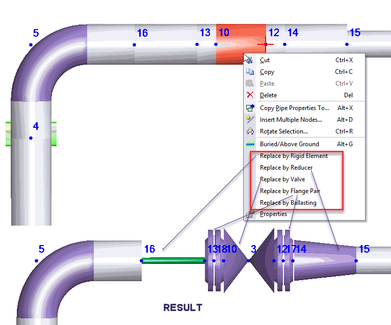
Added
new function to replace pipe or rigid element by pipe, rigid
element, reducer, valve, flange pair, ballasting weight
Fixed problem with
Ambient temperature Fixed
error "out of memory" in some big models Fixed
some problems with undo function Fixed
function for splitting bends Fixed
problem with cursor sticking  Fixed
problems with Vertical Order and Horizontal Order functions Fixed
other minor bugs |
4.83 R4, 28.02.2019
Updated
code ASME B31.8-2018 Added
ASME B36.10M-2015 and B36.19M-2004 standards into pipe database Added
Thermal Bowing effect modelling Removed
the limitation of static seismic analysis only for above ground
piping. Now mixed above ground and buried piping can also
be analyzed for seismic effects Fixed
problems with UNDO function Added
setting "zero projections for the new pipe" Improved
tee model. Now when you specify wall thickness of the branch
pipe greater than connected pipe, it is modeled with a thicker
pipe. The branch pipe stiffness become greater Fixed
other minor bugs |
4.83 R3, 28.01.2019
Improved
FEM solution methods. Now big models analyzed 6 times faster Added
automatic static seismic analysis for all ASME, DLT, GB, and
EN codes Fixed
problems with submerged buried pipeline Fixed
problem with calculation of maximum loads from all operation
modes in support local coordinates Fixed
problem with inserting nodes into bends and curved pipes Increased
the friction factor range up to 0.75 to model highly corroded
piping Fixed
other minor bugs (freezes, crashes, unknown errors) |
4.83 R2, 27.12.2018
Added
function, allows to replace the valve into rigid element.
It can be used to improve the model after importing from Caesar
II Improved
import from Caesar II function. Now it can convert nozzles
created using CNODE, reducers, rigid elements, code, insulation
weight, and more other improvements Start-Elements: Added ability
to automatically calculate the weld strength reduction factor
Wl for codes ASME B31.1, B31.3,
DLT 5366 Start-Elements: Added automatic
selection of the bend radius according to B16.9 for ASME,
GB, DLT codes GB/T 20801-2006: added calculation
of the stresses in test mode ASME B31.1: Code updated to
B31.1-2018 ASME
B31J-2017: added Errata to B31J-2017 from 11-9-2017 Seismic code SP
14.13330.2014 is replaced by SP 14.13330.2018 ASME B31.1,3,5,9,
GB 50316, GB 20801, DLT: Added option "liberal allowable"
for expansion allowable stress in project settings window Removed limit on
number of supports with gap Improved the additional
force-based loads input Improved the method
of slip joint modeling. Now guide support near the slip joint
is not necessary Improved the splitting pipe element dialog. Added
ability to insert any support from any node and other improvements Added additional
functionality to distance between nodes
function. Now it can calculate the pipe length between nodes Added ability to
see transparent piping model Added ability to
see SIF and k-factors right in the bend, tee and reducer properties
window Added ability to
place the supports in tees: sliding, springs, rigid rod hanger,
custom restraint Added two new isometric
views Added option "exclude
the pressure thrust force" in internal forces table.
No it can be used to determine the nozzle loads Fixed problems
with copying the materials between ASME and GOST codes Fixed problems
with rotating and moving using mouse wheel Fixed problem with
factor to friction in operating mode editor Fixed problem with
locking the springs in test state Fixed problem with
adding wind/snow/ice on piping with buried pipes Fixed problems
with export reports to Word (dxf) Fixed problem with displacements
in piping systems with constant springs Fixed
other minor bugs |
4.83 R1, 05.10.2018
Added
new pipe stress analysis codes and
filled corresponding material databases:
ASME B31.3 Process Piping
(USA) ASME
B31.4 Liquid Transportation (USA) ASME
B31.5 Refrigeration piping and heat transfer (USA) ASME B31.8 Gas Transmission (USA) ASME
B31.9 Building Services Piping (USA) EN 13480 Metallic Industrial
Piping (European Union) GB 50251-2015 Gas Pipelines
(China) GB 50253-2014 Oil Pipelines (China) GB/T
20801-2006 Process Piping (China) GB 50316-2008 Metallic Industrial
Piping (China)
Added
fitness for service code defect stress check GB/T 19624-2004
(China) Added
ability to use ASME B31J-2017 code
SIF and k-factors with all ASME, EN, DL/T, GB and GB/T code
series Added
4 new variable spring selection
tables Added
4 new constant load spring
selection tables Added
new constant load spring selection option "other",
that allows to select manually constant load springs by any
manufacturer Added
new database "Pipes". Contain pipe properties from
standards Added
new function to copy selected pipes
properties from current operation mode into other operation
modes Added
wall thickness check for pressure in occasional operation
modes Added
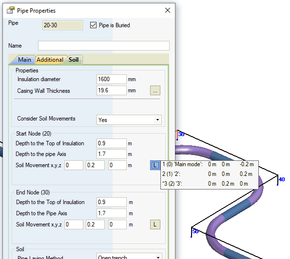
ability to set soil movements in X,Y,Z directions. It allows
to model soil subsidence, landslide, soil swelling, seismic
soil movements Added
ability to specify seismic accelerations manually, instead
of calculation by codes Added
ability to calculate several high-temperature modes. Creep diminish and creep self-springing
factors should be specified for each mode Added ability to specify
axial SIF for joints Added
ability to select node numbering step Added ratio (stress/allowable
stress) columns in stress tables Improved table "Load and
Displacement in Restraints". Now loads and displacements
are shown for all operating modes simultaneously Fixed
bug in additional force-based loadings. Moments was considered
incorrectly Fixed
bug in custom restraint containing single-directional restraint
and any other restraints with friction simultaneously Fixed
bug with buckling analysis in CJJ/T
81-2013 code Fixed
bug when some propertied are deleted while using undo and
redo functions Fixed
bug with program crash while using undo and redo functions Fixed
bug with saving pipe name Fixed several bugs
in project tree Removed
incorrect messages "Solution integrity check failed"
and "Iterations didn't converge" in some cases Removed
incorrect messages "Allowable load of springs in the
support is insufficient" in some cases Removed
incorrect messages "Material cannot be used at specified
temperature"
in some cases Removed
incorrect messages "Pipe wall thickness insufficient
for soil pressure" in some cases Improved
import from Caesar II module Improved
import from PCF module Improved
operation mode editor, fixed several bugs Improved
algorithm of soil supports placement Start-Elements: Fixed bug
in pipe loops calculation with nonzero pressure Updated
application guide Fixed
bugs |
4.82 R4, 17.05.2018
|
4.82 R3, 05.04.2018
Fitting
Database: Fixed insertion of equal tees Start-Elements: Fixed error
for buried pipes Fixed
some problems in project tree DL/T 5366-2014: Fixed displacements from
pressure loads in cold state and installation state Fixed
some other bugs |
4.82 R2, 05.03.2018
Test
state is now analyzed as an separate operation mode in Operation Mode Editor Improved
animation of deformed shape for additional force loads Caesar II import: Added import
of supports on bend nodes Caesar II import: Added import
of test mode Caesar II import: Some improvements Joint now can be placed into 3 pipes
intersection node Wind,
Snow, and Ice load code renewed ASCE 7-10 to ASCE 7-16 (USA) Wind
and Snow code renewed GB 50011-2001 to GB 50011-2010 (China) Import
from PCF: some improvements Piping
model: fixed bug in modelling of bends in inclined buried
pipes with inclined ground surface Piping
model: fixed bug in modeling of rigid rod hanger and variable
spring hanger in cold mode Fixed
some other bugs |
4.82 R1, 29.12.2017
Added
import from Intergraph CAESAR II.
START-PROF now can open Intergraph Caesar II neutral format
files (*.cii) Added
Smart Operation Mode Editor.
It is possible now to analyze several operating modes with
different temperatures, pressures etc. in one project file.
Also it is possible to add snow, ice, wind, relief
valve thrust forces,slug flow forces,
waterhammer forces, seismic and any other occasional load
cases Added
new element: Rigid Element Added
ability to convert materials between ASME B31.1, DL/T
5366-2014, RD
10-249-98 and other codes Added
automatic wind load analysis by following
codes:
ASCE
7-10 (USA), EN
1991-1-4:2005+A1:2010 (European Union), GB
50009-2012 (China), IS.875.3.1987
(India), SP
20.13330.2016 (Russia), IBC
2012, UBC
1997, AZ/NZS
1170.2:2011 (New Zeland), NBC
2010 (Canada), NBR
06123-1988 (Brazil), BS
6399-2 (Britain), TKP
EN 1991-1-4 2009 (Belarus), CNS
(Taiwan), NSR-10
(Colombia), KBC
2016 (Korea), Pressure
vs Elevation, Velocity
vs Elevation
Added
automatic snow load analysis by following
codes:
ASCE
7-10 (USA), IBC
2012, EN
1991-1-3:2003+A1:2015 (European Union), GB
50009-2012 (China), SP
20.13330.2016 (Russia), NBC
2010 (Canada), KBC
2016 (Korea)
Added
automatic ice load analysis by following
codes: Added cryogenic
piping analysis per GOST 32388-2013 Added
new database that contain bends,
tees and reducers properties from most of all Russian standards Added
natural arch of collapse consideration while calculating the
loads on the buried pipe Added option
to choose the constant force hangers and supports mode in
test state - fixed or not fixed Added ability
to model swinging stand Added ability
to insert pipe in two selected nodes. The new pipe will be
added between them Added ability
to add flanges in a valve and check leakage Pipe element
names are now printed in stress and internal force output
tables For
LISEGA, WITZENMANN, NBT 47039-2013, China Power springs added
the ability to see the maximum horizontal displacement in
spring table Now spring
properties transfer function transfer properties of constant
load supports and hangers Start-Seismic: Added seismic analysis
for FRP and plastic piping Start-Seismic: Improved seismic analysis
method for different codes ASME
B31.1: Added buried piping analysis ability. Stress check
performed according to VII-4.5, VII-5 ASME
B31.1: Fixed material properties for "A333 6" ASME
B31.1, DL/T 5366-2014: Added ability
to select different SIF factors joint
for element ASME
B31.1, DL/T 5366-2014: For custom
bend added ability to automatically calculate SIF and
k-factor as for ordinary bend DL/T 5366-2014: Added buried piping analysis
ability. Stress check performed according to CJJ/T
81-2013 ISO 14692: Added
option "Qualified tee" and "Qualified Bend"
for tees and miter
bends. The factors mpsb and mpst are affected by these
options during stress check ISO 14692: Added
option to consider axial force stress "Add axial force
and torsion stress" in Project
Settings ISO 14692: Added
ability to see all used equations and values in code stress
table ISO 14692: Added
ability to see stress color diagram in output
3D window Start-Elements: Fixed vacuum
tee analysis Start-Elements: Added pipe
wall thickness calculation for ISO
14692 and GOST
32388-2013 (Thermoplastic Piping) Start-Elements: Added pipe
and bend wall thickness calculation for ASME
B31.1 and DL/T 5366-2014 Piping
model: Now all gaps under 5 mm in guide supports are ignored.
Gaps in custom restraints are considered as usual. Also the
number of restraints with gaps shouldn't be over 50 Piping
model: Fixed hanger rotation effect calculation in cold
state Piping
model: Fixed analysis of piping containing only variable
spring hangers and supports Piping
model: Improved the spring selection algorithm. Now more
optimal springs are selected with lower allowable load In Project
Settings dialog codes list can be filtered by categories:
Power Piping, Process Piping, Gas & Oil Transmission Pipelines,
District Heating Piping Systems, Other 3D
view: Added ability to see the hidden markers in model
in 3D input window 3D
view: Fixed some bugs in 3D graphics 3D
view: Improved piping appearance in 3D graphics 3D
view: Fixed mouse wheel operation while working on two
monitors Optimized
the solution of the system of linear equations module. The
solution time is reduced 5%-60% Fixed
some bugs |
4.81 R4, 11.04.2017
Fixed
export to neutral file in Chinese user interface version ASME
B31.1, DL/T 5366-2014: Added 5D bends ASME
B31.1: considered Note 2 for 102.3.2 ASME
B31.1: Fixed the reducing tee Zb and SIF calculation ASME
B31.1: Fixed problem with pipe wall thickness check in some
cases CJJ/T 81-2013:
For test mode the allowable stress 1.5(St+Sc) replaced by
1.5St for fittings (bend, tee, reducer) CJJ/T 81-2013:
Pressure stiffening factor Omega for stress range SIF calculation
is now calculated as Omega=0.5*(1+Omega(P)) instead of Omega=1 CJJ/T 81-2013:
Added option to calculate stress for above ground piping according
to DL/T 5366-2014 DL/T
5366-2014: Expansion allowable stress is now calculated
as Sa=f(1.2Sc+0.2Sh) if SL>Sh Optimized
and reduced the memory usage for big models Optimized
and accelerated the program operation for big models Improved
China Power spring selection algorithm Insulation
weight for valve is got from matching pipe multiplied by 1.75 Fixed
valve, tee, reducer and flange weight calculation Fixed
solution integrity check for guide supports with a gap Fixed
the problem with stress calculation in intermediate cross-sections
of the bends in all codes (appear in 4.81R1) Fixed
the problem with resolution selection in export to graphics
file function (bmp, jpg, tif) Fixed some problems
with nonferrous material piping Fixed
the rejection thickness calculation bug with clipboard copying
of the data Fixed
the bug that lead to START-PROF crash in some models Fixed
some other bugs |
4.81 R3, 17.02.2017
Seismic
code SP 14.13330.2011 is replaced by SP 14.13330.2014 Improved
the automatic soil support placement on buried piping Improved
the closed circuit control accuracy Improved
the slip joint design control For
buried piping model added concentrated soil springs placement
near the resting supports, guides, custom restraints and direction
changes from 0.5 degree, removed near markers Added
ability to set the number of UNDO steps to zero. It is recommended to set the number of UNDO
steps to zero while working with very huge models. In this
case the UNDO functionality will be disabled and program will
work much faster Added ability to set the number
of messages in Error and Warning
window. It is recommended to set this value to
50-100 while working with
very huge models. It will make the program work much faster Added new pictures for Start-Elements ISO
14692 and GOST
32388-2013 plastic piping: Fixed the stress calculation ISO 14692: Added
new material Bondstrand 55, Fiber Glass Systems (NOV) for
25 years, filament Wound with Helical Angle 55 deg CJJ/T
81-2013: Removed the single use compensator stress range
check (E280) Fixed
some minor bugs |
4.81 R2, 01.02.2017
|
4.81 R1, 30.12.2016
Added
new code ASME B31.1 Power Piping (United states) Added
new code DL/T 5366-2014 Power Piping
(China) ASME
B31.1, DL/T 5366-2014: New materials
are added into START-PROF material
database according to ASME B31.1 and DL/T
5366-2014 codes ASME
B31.1 and DL/T 5366-2014: Added new
tee types: Weldolet, Sweepolet,
Extruded Outlet ASME
B31.1 and DL/T 5366-2014: Added new
bend type: Custom Bend with
ability to add used-defined stress intensification factors
(SIF) and flexibility factors (k-factors) ASME
B31.1 and DL/T 5366-2014: Added ability
to specify used-defined stress intensification factors
(SIF) and branch flexibility factors for custom
tees CJJ/T
81-2013: Fixed the allowable stress in test state for
long radius induction bends ISO 14692 and
GOST 32388-2013 plastic
piping: Fixed the stress calculation Added
tool tips for every cell in code stress
table with detailed information about equations and all
values used during calculation For
buried piping model added concentrated soil springs placement
in the points where soil subsidence changes a lot Fixed
the model of double-acting guide support on inclined pipes.
The inclined restraint is used instead of vertical restraint Fixed
the anchor load calculation in some models with slip type
expansion joints Added
pipe stiffness for tee header and branch is it have wall thickness
greater than the matching pipe Added
China General Expansion Joint (中国通用膨胀节数据库) into Expansion
Joint database Fitting
names are now printed in result tables like node names Fixed some minor bugs |
4.80 R2, 28.08.2016
START-PROF
doesn't support Windows XP any more. Supported operating systems:
Vista/7/8/10 Added
new option Start-Plastic piping.
It is possible to perform stress analysis for plastic piping
polyethylene (PE), polypropylene (PP), polybutene (PB), Polyvinylidene
fluoride (PVDF), polyvinylchloride (PVC) etc. according to
GOST 32388-2013 Added ability to specify names for
the nodal elements: restraints, bends, tees, expansion joints,
reducers and so on Added function for mirroring
the selected piping segment relative to arbitrary plane Added
application guide in START-PROF help system Added
new pdf user's manual Newly developed and replaced
the export to dxf (Autocad format) module Start-Seismic: Added new, more accurate
seismic stress summing algorithm. The seismic stresses are
reduced now Start-Seismic: Seismic displacements
now cut and can't be higher than specified gaps. The warning
message generated when beating in restraint with gaps detected
ISO
14692: Code updated to ISO 14692/Cor 1:2005 CJJ/T
81-2013: Allowable stresses in cold and test state is
1.5Sc and 1.5Sc now instead of 3Sc. The operation allowable
is 3Sh CJJ/T
81-2013: Updated material database per DL/T 5366-2014
instead of old DL/T 5366-2006 Added China power springs table to
springs database and added corresponding
selection algorithm Added Chinese constant force hanger
table NB/T 47038-2013 to constant
force hanger database and corresponding selection algorithm Code GB 10182-88 replaced by
NBT 47039-2013 in springs
database Piping
model:
Improved the nonlinear model iteration algorithm for single-directional
supports. Added solution integrity check Piping
model:
Improved soil spring placement algorithm for long radius bends Start-Elements:
Added centrifugal pump load check per API 610 (ISO 13709),
GOST 32601-2013 and Kellogg (L.C. Peng) Now
arch length of long radius bends is showed in 3D graphics
when show length function is enabled For
Rotate and Mirror
functions added ability to rotate pipe element uniform loads,
node concentrated forces, restraints in the custom restraint,
restraints in the custom expansion joint, nodal deformations,
restraint displacements Fixed
problem with appearing of empty standalone nodes after deleting
the piping segments Added
function that highlight the support
loads that is higher than specified allowable values Added
ability to place tees and valve between anchor and slip joint |
4.79 R3, 20.01.2016
Fixed
out-of-memory crash bug for very big models Improved
test pressure calculation for flange leakage check. The flange
pressure for test condition is divided by factor k=Ptest/Pope Start-Seismic: Removed unnecessary
error checks Start-Seismic: Fixed problem with seismic
anchor movement group number higher than 10 Start-Seismic: Fixed property copying
function from one pipe to others for seismic properties Start-Elements: Fixed virtual anchor length calculation
for buried pipe Fixed
analysis of models with custom restraints with elastic links
when option "fixed in test state"is enabled Fixed
problem with convergence of iterations for some models with
single-directional restraints (error "W541") Other
minor improvements and bug fixes |
4.79 R2, 08.12.2015
3D
view: Improved deformed shape animation for seismic load
cases Fixed
bug in intermediate anchor load calculation in local pipe
axes Start-Elements:
Improved the iteration algorithm for virtual anchor length
calculation Other
minor improvements and bug fixes |
4.79 R1, 11.11.2015
Translated
into Chinese language Translated into
English language Added
static seismic analysis for above ground piping (Start-Seismic
plug-in). Supported codes is RD 10-249-98,
GOST 32388-2013,
GOST R 55596-2013,
SNIP
2.05.06-85, SP 36.13330.2012,
CJJ/T
81-2013 according to
seismic code SNiP II-7-81*, SP 14.13330.2011, NP-031-01, GB50011-2001
(additional plug-in Start-Seismic) 3D
view: The custom restraints are now displayed more realistic
with real links directions Start-Elements:
Improved the calculation of pipe loops. Added the pressure
thrust effect and cold condition with friction forces acting
in opposite direction analysis CJJ/T
81-2013: Improved the calculation of pipe loops in the
Start-Elements.
Added the stress and fatigue check for the bends Piping
model: Added automatic markers placement. Now there's
no need to add markers manually Piping
model: In flange leakage analysis the longitudinal forces
are now displayed without pressure thrust forces effect Piping
model: Added ability to calculate loads on flanged connections
for high-temperature pipelines Soil
springs arrangement model: Added soil spring concentration
for the nodes with different soil properties on the both sides
(Insulation casing diameter, soil type, insulation type, cushion
presence, adhesion factor, pipe weight, submerged option,
settlement option) Expansion
joint and fiberglass material database are now open for modification Added
a new expansion joint deformation table
that allows easily to compare the design and allowable deformations Added
additional property for forged and welding tee - tee height Added
ability to change the pipe length in pipe
properties Added check box
"use the gaps" for the double-sided and single-sided
guides Fixed
other minor inaccuracies |
4.78 R4, 18.06.2015
Piping
model: Fixed inaccuracy for piping with variable spring
hangers and supports Piping
model: Fixed the soil springs placement in the bends when
it has been splitted manually Piping
model: Removed unnecessary fine soil spring mesh near
a some free nodes 3D
view: Fixed inaccuracy in deformed shape of piping near
the bends Fixed other minor bugs |
4.78 R3, 27.05.2015
Added
output of expansion joint displacements in operation condition
with pressure and operation condition with no pressure Added
ability to analyze buried slip joint without near standing
guide Added
ability to set CJJ/T 81-2013 as default in new project properties Fixed
bug with using old soil model for analysis with Single Use
Compensators |
4.78 R2, 21.05.2015
Piping
model: The stresses in bends are now calculated in 3 cross-sections:
two ends of the bend and middle point. For buried bends stresses
are calculated in several (more than 3) points along the bend
depending on the soil springs number Start-Elements: Fixed wall thickness
calculation for buried pipe. Now internal pressure + soil
weight case is taken into consideration 3D
view: fixed some bugs in deformed piping Fixed
disappeared warnings about longitudinal stability lost and
wall thickness for buried pipe considering soil weight + internal
pressure case |
4.78 R1, 22.04.2015
|
4.77 R2, 25.02.2015
Fixed
pasting of a disconnected piping when a base node is set in
the copied element Fixed
bug in inserting reducers or tees near other pipe elements Fixed
a bug causing an error, "This material cannot be used
for given temperature", when calculating rejection thickness Removed
analysis of insulation casing diameter for adjoining buried
pipes Fixed
problem with materials when calculating rejection thickness Added control on restriction
of application of reducer analysis methods Fixed a bug with variable spring
supports Fixed a bug with constant spring supports Fixed
other minor bugs |
4.77 R1, 06.02.2015
Added
"Belman" axial expansion joints for district heating
networks to database Implemented analysis of
several independent pipelines
simultaneously in one
file Added
paste function for independent pipelines Added
ability to insert both rotational and linear support movements
in a single node Updated
test state analysis. Branch bending is now calculated at test
temperature and pressure, rather than cold mode Completely
redesigned export to Word function. Tables are aligned by
sheet width and text is set to fit to cell Added
ability to export node names to dxf files Added ability to not set the
void factor, soil particle weight and the axial resistance
factor to the soils
database Updated the flange leak resistance
analysis methods. The minimum allowable pressure for flanges
is given, rather than
nominal pressure. Pipe
diameter and temperature are also deduced. Nominal
flange pressure must be
manually selected based on these data Optimized
graphics memory usage Start-Elements: Fixed
buried loop analysis Fixed
other minor bugs |
4.76 R3, 21.11.2014
Improved
analysis of stress in tees Fixed
bug in analysis of eccentric reducers Added
ability to insert pressure balanced slip joint. Slip joint
cannot be buried and can only be placed on above-ground pipe
elements Fixed
highlighting error in the stress table for test state Fixed
recurring error with the quality factor of branch welds Fixed
other minor bugs |
4.76 R2, 07.11.2014
Fixed
a bug in the analysis of pipelines containing slip joint Improved
work with models containing a large number of nodes and a
large number of degree of freedom Fixed
a bug in load analysis for local support axis in test state Fixed
bug in analysis of pipelines containing guide support with
a 0 friction factor Fixed
a bug in the analysis of the stress intensification factor
in fabricated tees using GOST 55596-2013 and CJJ/T 81-2013 Fixed
other minor bugs |
4.76 R1, 01.10.2014
Added analysis using Chinese
standards CJJ/T 81-2013 District heating networks Added
Chinese GB 10182-88 to the springs database and added
the ability to select variable spring hangers using GB 10182-88 CJJ/T
81-2013: Chinese
metals added to materials
database CJJ/T
81-2013: Added insulation weight based
on Chinese standards and the HTN manufacturer CJJ/T 81-2013: Added
additional analysis of local pipe wall stability using
EN 18941-2003 in addition
to CJJ/T 81-2013 Start-Elements:
Added relative displacement analysis for single use compensators
using GOST R 55596-2013 Start-Elements:
Adjusted analysis of distance
between supports using GOST R 55596-2013 Added
ability to analyze single-directional guiding supports placed
on inclined pipe elements up to 18 degrees from horizontal.
The friction field is horizontal Added
ability to analyze double-acting guiding supports placed on
inclined pipe elements with any angle from horizontal, including
vertical. The friction field is along the pipe Fixed
bug with inverted display when importing to .bmp Fixed
other minor bugs |
4.75 R2, 08.09.2014
Fixed
a bug with equivalent number of full cycles Fixed
copy and paste issues Start-PDMS-B: Fixed
exporting error causing branch end elements to not load properly |
4.75 R1, 08.08.2014
|
4.73 R1, 04.04.2014
|
4.72 R3, 12.03.2014
Improved 3D view print quality Added analysis name when printing Added
font size settings
for display and for printing Fixed
bug with load analysis for
local restraint axis Fixed bug causing empty pop-up
windows Fixed
lag problems encountered on some systems Added
restriction:
a warning is displayed
when spring load range exceeds set value Added
restriction:
material name cannot exceed 16 characters Added
restriction: warning
when piping ends are left open Minimum
wall thickness is set with a 3%
margin, if this is specified in standards Increased display
speed when switching between graphic windows Increased 3D view loading speed Increased
analysis speed Added
x symbol for selected node,
which blinks when necessary for easier detection Added
coordinate axes when printing and exporting to .bmp files Added display of the number
of unknown variables after an analysis in the errors and warnings window Fixed scaling bug with node
elements in 3D view Restored
"Select all"
function Fixed
other minor bugs |
4.72 R2, 09.01.2014
|
4.72 R1, 23.12.2013
Completely
redesigned 3D view Added button to display the springs database
from variable spring support and hanger settings "Other" added for
spring
standards Added
ability to input carrying capacity
for user's springs Density added to materials
database Added ability to automatically
calculate pipe weight based on material density Added the 1.6 minimum gap restriction
for custom restraints. This restriction
remains for guiding supports Improved
convergence of iterations for single-directional restraints.
If an amplification algorithm is used the following message
is displayed: "allowed support subsidence is considered".
This
is a notification only START-PROF
interface view is saved only when
"View - Save current environment" is selected Start-Elements:
added ability to turn off minimum wall and element thickness
restriction Fixed import of properties files
to the materials database Create list of pipe elements-
fixed generating for reducing
tees Fixed
other minor bugs |
4.71 R1, 02.07.2013
Added
support for Windows
8 Added ability to select
WITZENMANN constant
spring supports and hangers
Uniform
product weight and density added for large-radius bends and
branches Strengthened
depth accuracy control for buried elastic bends Perfected
iteration algorithm for single-directional restraints. Improved
convergence, the "insufficient support load" warning
appears less often Added
ability to sort nodes when exporting to Word Fixed
bug when setting resting support load for local restraint
axis in nodes with valves Fixed
bug with allowance for corrosion and mill tolerance when checking
wall thickness of vacuum pipe elements and their stability
analysis in START-PROF Fixed
bug with analyzing custom restraints containing spring supports
with gaps Fixed
insulation stress analysis when the piping models contains
both PUR and PPM pipes Fixed
bug causing the errors and warnings window to not appear
after analysis Fixed
the setting of density as 0 when opening old START-PROF files Removed
stability analysis for above-ground pipe elements of above-ground
pipelines Fixed
other minor bugs |
4.70 R2, 20.11.2012
Added
restriction: pre-tightening cannot be input for custom restraints
without springs Added
restriction: maximum of 10 spring chains per variable spring
support Added
restriction: gaps
of less than 1.6mm
for pipes with D<125mm
and 2.0mm for pipes
with D>125mm
are not considered in
the analysis Fixed
load analysis for local restraint axis for buried sliding
and guiding supports Updated
WITZENMANN expansion joint selection algorithm Changed output table format
for displacements, support
loads,
relative
displacement of expansion joints, forces.
Added ability to sort, interactive selection of coordinate
system, analysis state, filter for support and node element
types. Added node element name column Fixed
other minor bugs |
4.70 R1, 25.09.2012
Start-Elements:
implemented analysis for pump
loads Added WITZENMANN springs to the springs database.
Implemented algorithms
for selecting
WITZENMANN springs
and their tightening Disabled
selection of variable spring supports in PDKON state Added
restriction for soil codes and other properties of pipe elements
adjoining bends Added
ability to open and save open-format files using "File-Open" and "File-Save
as..." Added
bookmarks, with the ability to adjust bookmark display and
docking
Added ability to input product
density and implemented automatic analysis of uniform product
weight in pipe
properties Increased
maximum wall thickness from 99mm to 210mm Added
automatic removal of inccorect elements (0 distance, duplicates,
etc.) prior to analysis Fixed
other minor bugs |
4.67 R3, 25.01.2012
|
4.67 R2, 14.12.2011
|
4.67 R1, 28.11.2011
In Start-Elements, added consideration
of branch stress in gauge analysis of U-, L- and Z-shaped pipes Added properties of standard
WITZENMANN axial, angular and lateral expansion
joints to expansion joints database Improved input dialogues for
custom restraints
and custom expansion joints.
Friction restraints are now set automatically Gaps can now be inserted for
guiding
supports Changed analysis of guiding supports: 1
- friction is considered along the vertical
plane of lateral supports, as well as the horizontal support
plane; 2 -
lateral restraints and
friction are still in effect when vertical restraints are
disabled. To get results equivalent to old analysis versions,
when opening START-PROF 4.66 or lower version files, guiding
supports can be set to be automatically converted to custom
restraints, according to the old modeling version for guiding
supports. This
change is not reversible - when a single-directional guiding
support is disabled, 4.67 analysis results will always be
different from 4.66 and lower. Added ability to input restraints
with gaps for custom restraints Added pipe element names. More... Switched to Unicode.
START-PROF is now displayed correctly on Russian versions
of Windows Fixed bug with
cold mode analysis when supporting forces and flexibility
is set for all springs Added "support loads for
piping axis" table, where support loads along and perpendicular
to the piping axis and vertical support loads are displayed
automatically. A 0.8 load ratio for intermediate supports
to the left and to the right can also be automatically considered
using section 8.44 SNIP
2.05.06-85 Added "double-acting intermediate support
loads" table Fixed bugs with bend stability analysis.
Added analysis for concave bends. Added "laying type"
to project
tree - buried,
above-ground and "node" Fixed bugs with displaying displacements
in the displacements
panel Fixed other bugs and made improvements to the
output 3D view Added export
to (bmp)
function with any resolution Fixed bug with the analysis of spring load
variation percent in cold mode Added restriction
that materials database can only be edited if stress units
are set as MPa Improved zoom function. A rectangle of any ratio
can be selected |
4.66
R1, 17.02.2011
Added ability to input ballasting weights for ballasting analysis of transmission
pipelines Implemented analysis of piping
float in flooded soil (e.g. swamp) Added ability to consider vehicle
load on buried pipelines in Start-Elements Added ability to select
safety factor for pressure
loads - 1.1 or 1.15 based on table 13 (previously it was always
set at 1.1) Added analysis of circular standard
pressure stress to prevent not allowable plastic deformations
in buried and above-ground pipelines using (30) section 8.26 Buried pipeline stress analysis
is now automatically performed using standard loads - section
8.26 formula (29) Tees and branches stress analysis
is now automatically performed using standards loads and yield
limit is set as resistance, using section 8.64 Equivalent fibre stress is now
different for compressed and stressed cross-sections Pipe and fittings weight is
added for buried pipelines Implemented analysis of buried
sliding and guiding supports Start-Elements:
Added ability to input expansion joint dimensions considering
restrictions for axial loads on lateral supports When the "set in test state"
option is selected for custom restraints, variable
spring supports are transformed to single-directional restraints (as opposed to double-acting
in prior versions) Added ability to input effective
field and analyze pressure thrust force for custom
expansion joints Automatic end analysis is run
to take into account nonlinear effects when selecting variable
spring supports and hangers in cold mode. There is no need
to perform an additional analysis manually. More... Added ability to work with pipelines
containing several independent pipe elements. More... Added ability to highlight a closed circuit
when a disconnect is detected, in order to easier locate the
problem Added "check rotational
displacements" option for axial expansion
joints Added databases for axial, one-time,
rotational and lateral
expansion
joints Changed distortion restrictions
for axial expansion
joints Added rotation function "as in Autocad": Shift + press rotate mouse wheel Added restriction: average and rest factors
for pipes adjoining tees must be set or not set Added restriction: friction factors in friction
restraints in custom restraints must be the same Added ability to simultaneously delete multiple
selected pipe elements Fixed straight stub-in analysis when branch
and header thickness differs Fixed bug with export to Microsoft Word 2010 Implemented ability to update START-PROF.
Prior versions no longer need to be deleted before installation Implemented installation using
ActiveDirectory, which
allows remote
installation on multiple platforms |
4.65
R2, 30.09.2010
Fixed
bugs with inputting dimensions in cylindrical coordinates Fixed
bug causing warning about supports being placed too close
together (less than 5D) Added
ability to place stub-ins at close distance (from 1mm) |
4.65
R1, 12.08.2010
Added
automatic allowable load
analysis for supports
and equipment. If allowable load is exceeded, a warning is
displayed Added
ability to switch between two iteration formulas for analysis of pipelines including
single-directional
restraints and friction. More... Added
automatic placement of caps in all end nodes. More... Added
option to toggle comparison of wall thickness with minimum
allowable value on/off (in Start-Elements). More... Added automatic replacement
of selected variable spring supports with custom restraints.
More... Added
warning after spring selection if the number of spring chains
exceeds the value set in input
Material
and soil properties
are now saved to
"ctp" files.
When opening a material
or soils file, a dialogue offering to input new elements into
the database pops up. If
the materials or soils in the file are present in the database,
but their properties differ, 3 options are available:
update database properties,
add element to the database
under a new name, or
delete the element in the file and use properties from the
database Material and soil properties
used in the analysis are now saved in open
format files For
easier input of elements for transmission pipelines (where
plan and profile are used as input data) implemented input
of dimensions in "cylindrical" coordinates.
Pipe element dimensions are set as a projection
on the XY plane, projection
on the Z axis and the two angles between the XY projection
and the X and Y axes Added
automatic replacement of commas to periods in text fields.
Data can now be entered using the number pad when the keyboard
language setting is set to Russian Added "display" function
for project
tree Added ability to automatically
insert
U-shaped expansion joints in one node Added
ability to determine element wall thickness in vacuum in Start-Elements |
4.63
R2, 09.03.2010
Fixed bug with
forged tee analysis Fixed bug
with warnings about supports (no
convergence of iterations) Fixed bug with
resource analysis for austenitic metal elements Fixed other minor bugs |
4.63
R1, 18.02.2010
Added warning regarding not
following standards Added ability to insert
double-acting guiding
supports and other restraints
in nodes connective buried and above-ground pipeline elements Updated
tee weight analysis: added
"header length"
for welded and extruded tees. The
weight of straight header pipe elements is deducted from input
tee weight Updated
valve weight analysis:
the weight of straight
pipes with length equal to valve
length is automatically deducted from input
valve
weight Added option to fix all springs in custom
restraints in
test state analysis
Fixed
bugs with automatic recalculation
of product and pipe weight. More... Disabled
rounding-off of wall thickness and corrosion allowance when
saving Successful
software test in Windows 7
Added
ability to insert
and move
intermediate nodes in
branches Added
ability to automatically
analyze tee weight. More... Added new rotation option in
3D view - "cylindrical".
More... Added
ability to view depth
of pipe laying, water
height and subsidence
(displayed as lines above each pipe element) in 3D.
More... Improved the "properties"
menu. During automatic pipe and product
weight recalculation by
density, pipe and product weight is calculated independently
for each pipe element based on its properties Added option
to synchronize
3D view
and output
3D view |
4.62
R4, 07.09.2009
|
4.62
R3, 08.06.2009
Fixed bug with selecting LISEGA
springs Fixed bug with pressure analysis for above-ground expansion
joints and pipes in Start-Elements and
Start-Express Fixed editing
of pipe element and fitting properties for a category of elements
(bug appeared in
4.62 R2) |
4.62 R2, 19.05.2009
|
4.62
R1, 05.05.2009
Added option for bend analysis:
PEX crosslinked
polyethylene and
corrugated steel (ISOPROFLEX, ISOPROFLEX-A, KASAFLEX) Added PPM insulation: Made
additions to the insulation weight database,
added PPM insulation stress analysis, added consideration of PPM-insulation
in buried pipeline
forces analysis Added LISEGA springs
to springs
database. Implemented
LISEGA spring
selection and
tightening Added
ability to input three
projections for "pre-tightening" in custom restraints, which is necessary, for example,
for inputting horizontal and inclined LISEGA variable
spring supports Added new standard support -
"double-acting guiding".
Unlike a single-directional guide support, a double-acting
guiding support restricts upward displacements Deformed shape are now built taking into account evenly
uniform load on pipe elements Displacements
table now displays displacements in branches Added spring
allowable load conditions analysis, where properties are input (rather than set automatically) Added
ability to input
flange
pairs Added new restraint -
Marker,
used to improved analysis
accuracy in certain cases Displacements
table is now always produced for all nodes.
There is no need to select
it Added
table for "loads and displacements
in restraints" analysis
output. Improved "properties" menu. Added
cell displaying multiple properties (e.g., diameter
of 219 and wall
thickness of 6 are
displayed as "219X6"). Also
added ability to
automatic change properties
for a category of selected pipe elements, which can be used as an alternative to
"copy
pipe element properties". More... Improved buried pipeline analysis
methods. Added
the "unit weight of solid" property in soils
database Added display of displacements
in the displacement
window in work,
cold and present state
When
working with a network key, you can now run any number of
copies of the software on local workstations, using a single network license Added
ability to input
node names, which are displayed in all output tables
and in 3D view Added
search
nodes by name function Added
input node numbers
function Added
change
angle between
pipe elements function Added
options
to automatically delete
and copy properties of selected springs in variable spring
support properties For
long
radius bends and
prestressed
bends added
ability to split,
insert,
move
and delete nodes.
More... Improved elements,
fittings and supports tree. Fitting
and support types are now displayed Added kN, kN*m, kgf*m, N*cm, cm^4
measurement
units Added ability to delete a selected category of supports or
fittings Added
ability to copy
fittings data from/to
START-PROF and
Start-Elements. More.... Made
additions to electronic help Fixed other minor bugs Added
autosave
|
4.61 R3, 22.08.2008
Fixed minor bugs (error
and warning display, etc.) |
4.61
R2, 20.08.2008
Fixed
maximum temperature display in temperature history Fixed
input of "welded
joint pressure strength factor" of less than 1 Fixed pressure
analysis for forged tees
(taking into account the
length of the adjoining pipe element) Changed
analysis methods for resistance to external overpressure
(vacuum pipe elements) Error
message "Adjoining
elements must have identical properties (uniform weight
of insulation)"
for branches changed to warning Removed
error message "Adjoining
elements must have identical properties (pipe material)" for stub-ins. Stub-in
analysis is now performed taking into
account different header and branch materials Set
stricter restrictions on input data (pad width for stub-ins and fabricated tees,
length of buried pipe elements) Fixed other minor bugs |
4.61, 27.06.2008
Added
automatic consideration of pendulum
effect in variable spring hangers
(rod displacement from vertical). START-PROF 4.60 and lower
files set rod length as 0 by default (pendulum effect is not
considered) Added
automatic consideration of friction in variable spring supports.
START-PROF 4.60 and lower files set the friction factor
as 0 by default (friction is not considered) Added
new element - cap.
Using caps allows more accurate modeling of internal
pressure thrust loads on supports and equipment connections.
START-PROF 4.60 and lower files automatically
place caps in all free end nodes (without supports or fittings).
See pressure
thrust force and bourdon effect All
branches are now analyzed
for bending and internal pressure. Branch types are changed
from "bend", "flange", "welded"
to "elbow", "bend", "miter",
"extruded". New properties
are added for branches (number of miter joints, weld quality
factor, presence or absence of flanges, weld position relative
to branch plane). START-PROF 4.60 and lower files use bends
for branches with a radius of less than 2D
and branches with flanges, while branches with a radius of
more than 2D are
changed to bends. Welded branches are replaced by miter branches,
where the number of miter joints is automatically determined
in order that the skew angle is 22.5 or 15 degrees. We
recommend reviewing, and if necessary editing, outdated file
versions. Total
allowance is
change to two parameters for all pipes and fittings
- "corrosion allowance"
and "mill tolerance". START-PROF
4.60 and lower files automatically
set mill tolerance as
10% of wall thickness,
while the rest of total
allowance is taken as corrosion allowance. Mill tolerance and corrosion tolerance combined
always equal total
allowance. We recommend
reviewing, and if necessary editing, outdated file versions. Added
pressure analysis
for miter and extruded
branches using RD
10-249-98 in Start-Elements
and Start-Base Changed restrictions for
axial expansion
joint skew.
Equivalent axial displacement
from rotational deformation cannot be more than 5%
of allowable axial expansion
movement Loosened restriction for pipeline
turning point angles with large radius bends (0.07 degrees) Improved single use compensator analysis in Start-Elements Longitudinal
weld quality factor for
fabricated tee and stub-in analysis
is now always set as 1 Added wall thickness pressure
analysis in Start-Elements:
Expansion joint and pipe analysis
Tested
for Windows Vista Added
insert U-shaped
expansion joint Added
ability to sort
element list
by any parameter by clicking
on it in the heading Selecting a row in the element
list highlights the
corresponding element in 3D
view The element
list table width is
reduced Improved stress output menu for fittings. Added
forces for all adjoining elements and made the organization
more user-friendly 3D view zoom can now be controlled with
the mouse wheel Added project
tree. Elements can
be selected by
property (pressure,
temperature, wall thickness, etc.) Added ability to input service
life in hours in Project
Settings Branch dimensions are determined
automatically by adjoining elements for extruded tees Improved measurement
of distance between nodes Added
ability to edit
type for a category of fittings. For example, all forged tees of a certain
type can be changed to stub-ins Added ability to copy and insert node fittings from context menu Improved rotation Improved insert
node function Improved move
node function Friction
factor in all restraints can now be from 0.05 to 0.4 Standard
guiding supports can
now be placed on elements with a 0.02 incline Set
stricter restrictions on input data Added collision
restriction for inserting
new elements. Creating
closed contours is now more user-friendly. In case of overlap, the option to insert
a new node is presented Added
ability to copy
tees
and branches from
Start-Elements
to nodes in
START-PROF Fixed
bug with load strength analysis for
equipment in local coordinates. All
loads in all states are first transferred to local coordinates,
then strength is determined
(as opposed to selecting strength first and transferring it
to local coordinates, as in prior versions.) Fixed other minor bugs |
4.60
R393230, 30.01.2008
|
4.60 R393229,
25.12.2007
Improved
help Fixed bug with
variable spring support and
hanger analysis Fixed bug with
custom tees Fixed
bug with copying diameter and wall thickness into other elements Fixed
R1 factor in SNIP
for buried pipelines. Implemented
amendment 1 section 8.35 for
strength requirement warnings Fixed
bug with saving in local coordinates for support loads table Fixed other minor bugs |
4.60 R393227,
16.10.2007
Selection
mode is turned on by double clicking on an empty space in
3D view Fixed bug causing error: "fitting is bigger than adjoining elements" Improved
help Fixed bugs with
displaying displacements in arbitrary points along the
branches length in output
3D view, and with updating
displacements if local coordinates are selected Fixed bugs with
analysis of pipelines containing guiding supports For
austenitic steel piping with
a temperature above 370 degrees,
the warning that relaxation and averaging factors must be
set is no longer displayed Fixed bug with
copying elements with dimensions set in angles or projections Fixed bug causing error: "expansion joint skew is not allowable" Fixed other minor bugs |
4.60 R393225,
15.09.2007
Added ability to copy and paste fittings and supports Last
node is automatically selected after inserting an element Node
numbering step can now be set when splitting an element Added
"length" to element properties Fixed bug with
working with Windows
98 Fixed other minor bugs |
4.60
R393216, 15.08.2007
Added
ability to display deformed shape of the piping
from input loads and forces. Changes
when going from test to work to cold mode can be viewed as
an animation Added
detailed context help. Answers
to frequently asked questions and theories behind methods
used in START-PROF can be found here. Search function is also available Removed
node number restriction.
Up to 32000 nodes are now allowed Removed
all restrictions on the number of materials, end nodes, cross-sections, branches types, soils,
etc. Removed
restriction requiring the presence of at least one anchor Improved
analyses to allow START-PROF to
run faster Added
buried bend
stability analysis in
Start-Elements Implemented adjusted methods
of analysis for distance
between Single Use Compensators in Start-Elements.
Distances are now bigger Changed tee stress analysis
methods: forces and stress are now calculated at the connection
point of branch and header, not for header and branch axes
intersection point Added consideration of
soil subsidence
for buried pipelines Added
ability to set
support displacement
independently of adjoining
equipment in test and operating mode and other forces
(for example, support
or equipment subsidence) Added
allowable
deformation and skew restriction
for axial, rotational
and lateral expansion joints Added
ability to display
specs
for all elements and fittings Added to the insulation database.
4 new insulation
types for heating networks
are added: mineral
wool with asbestos-cement
plaster and fibreglass Improved input restrictions Added restriction on proximity of single-directional restraints
and other restraints Added restriction on branch weight, allowable
support displacement , etc. Added
warnings and error messages Improved interface to
be more user-friendly Improved
menu display, pictograms, etc. Added "errors
and warnings" window for
input data analysis
and for output.
The element or node with
the error can be selected by clicking on the message, while
double-clicking brings up the properties or results table Added
ability to copy and paste from one START-PROF window to another Added ability to insert fittings and supports into a selected
group of nodes Added
tabbed view Added option: "always calculate displacement
in nodes" in
properties "Apply" button added
to element
properties menus Added
ability to set save preferences Added
ability to calculate
distance between
nodes Branch weight is now automatically
calculated and can be viewed in branch
properties Improved
setting of center for rotation Added ability to rotate around a selected point Tables
of displacements, expansion joint deformations and support
loads can now be printed in global or local and global coordinates Other
interface improvements, fixed
other minor bugs |
4.50R327681, 15.11.2006
Fixed bugs with
3D view when using "edit
element" Implemented work with two monitors Fixed
bug with transferring data from PCF ("Start-PCF") Added
pad thickness and width restrictions for tees Restored
ability to insert valves
in buried pipelines |
4.50 R327680, 16.06.2006
Improved
stress analysis methods for tees and
branches – higher stress
process piping elements; Various
mechanical properties are
considered for stress analysis of seamless and welded pipes
and fittings; Added
recommendations for stress and local stability analyses of pipelines under external overpressure
(vacuum pipelines). Improved stress analysis
for gas and oil transmission
pipelines Adjusted
overpressure stress
analysis of piping
elements For pipelines with PUR-insulation
added insulation stress analysis Improved stress output
table Change
allowable stress for
buried pipelines Added
ability to analyze stability of buried
bends Made
changes to the materials database Improved
interface Improved toolbars,
menus, etc. More user-friendly input and
output analysis due to the ability to switch between
global and local coordinates Fixed
other minor bugs Changed
the functioning of guiding supports. When single-directional vertical restraints
are turned off, lateral restraints switch off automatically |
4.46 R262205, 04.07.2005
|
4.46 R262150
14.05.2005
Adjusted
stress analysis methods for tees and branches in district
heating networks. Safety
margins for static stress and fatigue failure analyses were reduced, which
allows the use of thinner branches and tees Added
Start-Pro (in addition
to Start-Lite), where
restrictions on the number of elements are removed.
This is especially applicable
for large buried heating networks Implemented analysis of buried
transmission pipelines and heating networks with large radius branches
and bends Added ability to wedge or not
wedge variable spring supports in test state (previously,
they were wedged automatically) Nodes with deformation and additional
loads are now marked in 3D
view. Made changes
to the materials database,
which allow adjusting
the analysis using appropriate standards Unified Start-Elements
and Start-Express
interfaces Reformatted
and corrected materials database Implemented new weight analysis in operating mode Adjusted PUR-insulation stress analysis |
4.45, 28.05.2004
Added insulation
to databases.
Database includes weights
for common insulation types for pipelines with a diameter
of 50 to
1000mm. To set
insulation weight for
pipe length, simply press "..." and select insulation type. Previously, insulation
weight was input manually.
The database is open and
can be edited Adjusted
interaction with soil for buried pipelines Trench
width is no longer input Stress from soil weight was reduced due to reduction of safety margins Added insulation
stress
analysis for buried pipelines
with PUR-insulation,
where stress is soil pressure A
network version of START-PROF can
now be installed Added Start-PDMS, for importing data from
PDMS to START-PROF Added
casing thickness and removed trench width in Start-Open format |
4.42,
11.09.2003
|
4.40, 10.12.2002
Adjusted analyses in
Start-Base
and Start-Elemen ts To
bending stress analysis for tees and branches To
analysis of interaction with soil for pipes with industrial
polyurethane insulation Added
non-parallel shoulders for analyses of buried U and
Z-shaped elements Added Start-Nozzle to Start-Elements,
which allows flexibility
analysis of piping stub-ins into various vessels and equipment.
Analyzed using
WRC-297 and BS-5500 Improved
3D view, added
dynamic rotation, move
and zoom Added Start-Word,
which allows export from
START-PROF to Microsoft Word |
4.38, 01.07.2002
|
4.37, 21.05.2002
Took
into account the increasing flexibility of non-uniform strength
tees Implemented
Start-PCF, allowing the
import of ISOGEN 3D piping models into START-PROF (including PLANT4D and PlantSpace Design
Series) Included
new installation packet |
4.35, 14.02.2002
|
01.04.2000
|
1994
|
1992
|
1976
|
1972
|
1969
|
1965
|

