

Read about START-PROF pipe stress analysis software
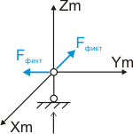
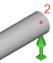
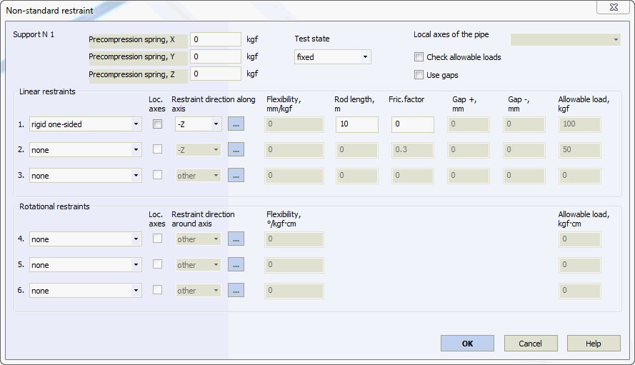
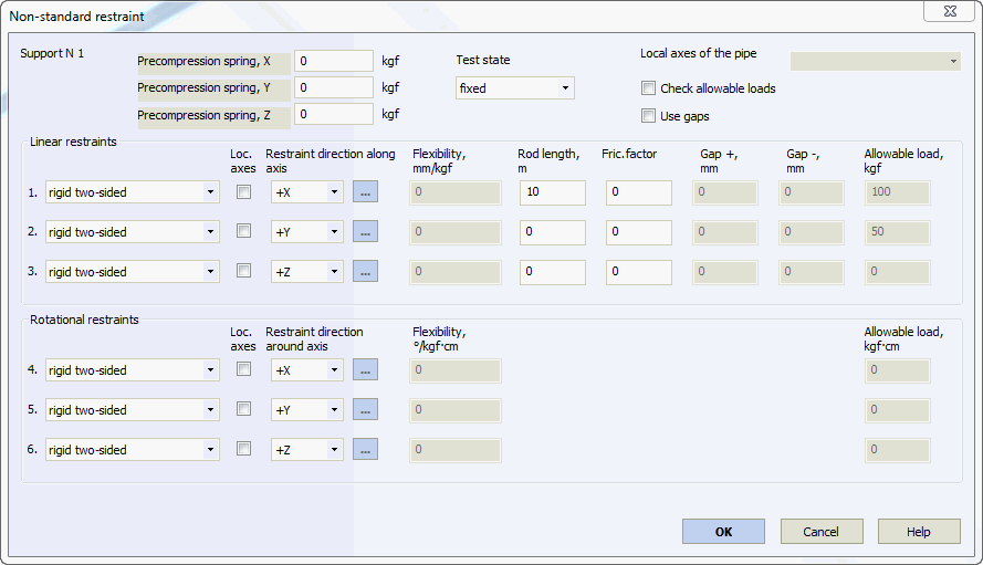
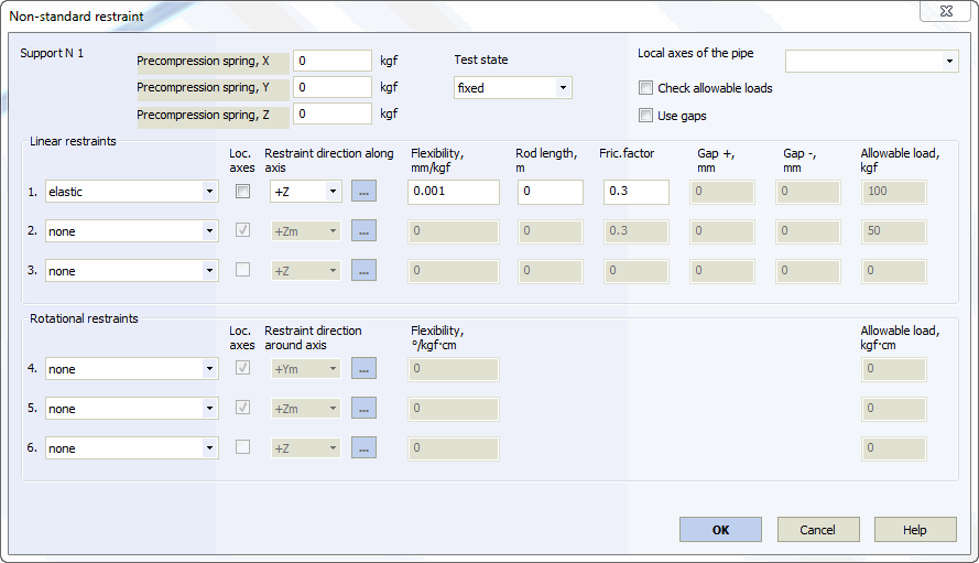
Modeling a rigid rod hanger taking into account the pendulum effect is displayed below. The hanger is disabled with upward displacement.

All 3 linear displacements and 3 rotational angles are restrained.
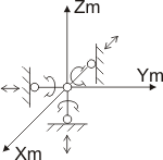
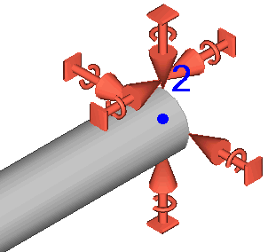
Horizontal and vertical displacement perpendicular to the pipe axis is restrained. Longitudinal displacement is not restrained. Pipe friction against a side surface with a factor of 0.3 and horizontal surface with a factor of 0.1 is also considered (rollers).
Guiding support without rotation restraints with different side and horizontal surface friction factors:
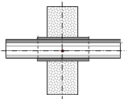
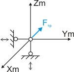
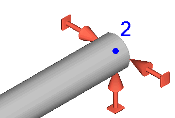
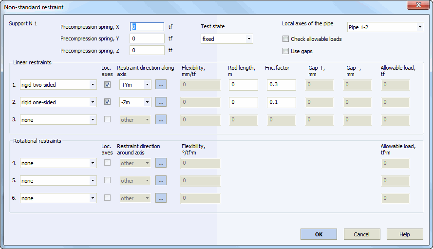
Guiding support with rotation restraints with the same friction factors (does not restrict torsion)

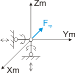
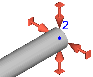
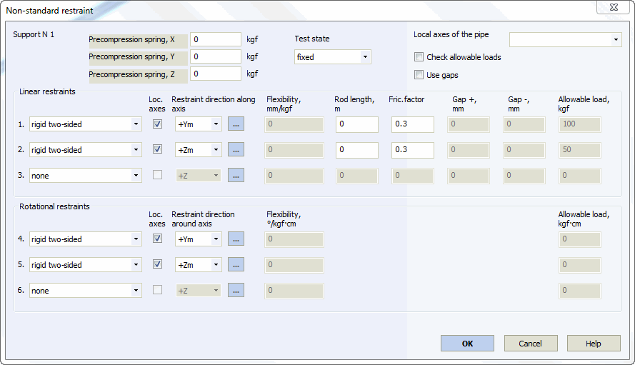

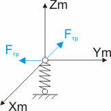
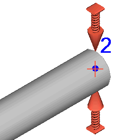
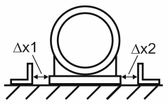
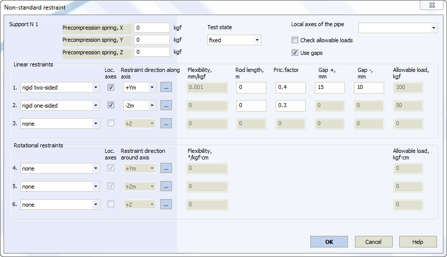
Support is disable with upward displacement. Gap to the left is 10mm, to the right is 15mm. Friction factor against the horizontal surface is 0.3, and against the stop side surface - 0.4.
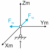
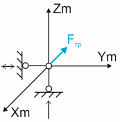
If the pipe does not touch side stops, it functions as a resting support (left image); when it touches the side stops, it functions as a guiding support (right image).
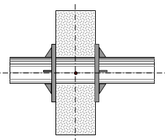
Initial pipe position is 20mm and 30mm horizontally from "window" walls and 10mm and 15mm vertically.
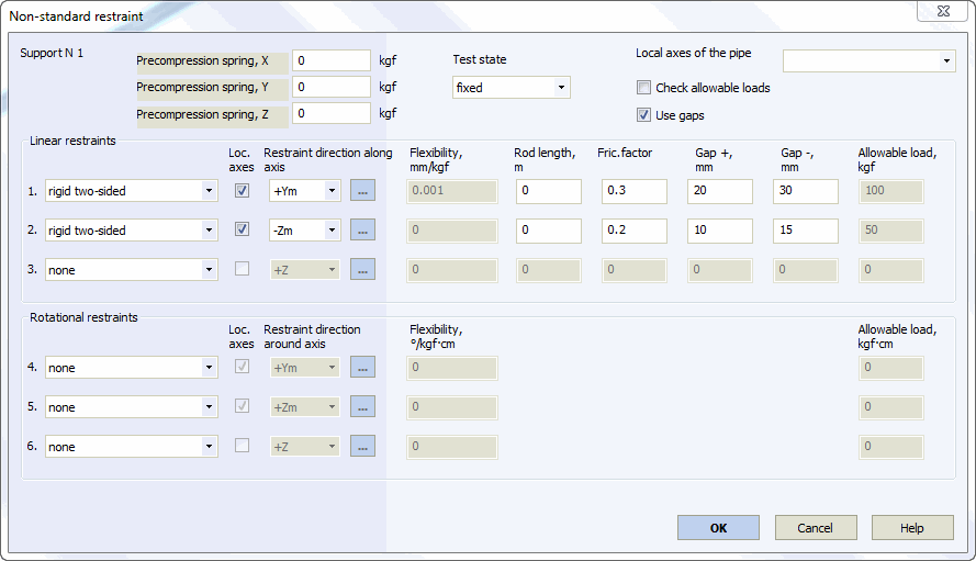
Restraint functions as follows (models shown below from left to right):
version 1. Pipe does not touch "window" walls. All reactions are equal to 0, there is no friction
version 2. Pipe touches the lower "window" wall. There is friction against the horizontal surface (friction factor 0.2)
version 3. Pipe touches a side "window" wall. There is friction against the vertical surface (friction factor 0.3)
version 4. Pipe is in a corner of the "window". There is friction against the vertical surface (friction factor 0.3) and the horizontal surface (friction factor 0.2)
