

Read about START-PROF pipe stress analysis software
Piping to equipment joint points can be modeled as fixed anchors in stress analysis piping models. This adds a strength margin for expansion stress estimation. However, this can lead to significant overestimation of the calculated loads transferred from the piping to equipment. Taking into account the actual flexibility of the piping to equipment connection allows to significantly reduce these loads.
An universal method for determining nozzle flexibilities is using the finite element method (FEM). PASS/Nozzle-FEM is a program designed to calculate the stresses and flexibility of nozzle-to-shell junctions using the finite element method. It also calculates the nozzle’s allowable loads and estimates the strength of the junctions for a wide range of geometric configurations and operating conditions. The program helps engineers to provide higher levels of equipment safety while reducing labor costs at the design stage. It is intended for use by equipment and piping designers and mechanical engineers and can help them to quickly check and satisfy requirements for loads on pressure vessel/equipment nozzles, as well as on non-standard piping fittings. It is recommended for use in design and industrial safety reviews in oil and gas, refineries, petrochemical, chemical, power, and other industrial facilities. It can also calculate the SIF and k-factors for tees that are not covered by ASME B31 codes such as lateral tees and tees with D/T>100.
Unlike other widely available FEM programs, PASS/Nozzle-FEM does not require special training and can be used by any mechanical engineer. It automatically creates the FE mesh and estimates the calculation results.
The approximate semi-analytic methods, like WRC 297 and PD 5500 are still popular, because it doesn't require to buy the FEM software and allows you to get the result much faster. But semi-analytic methods has the limitations, and has lower accuracy of the results. PASS/Nozzle-FEM can be used instead of WRC 297 and PD 5500 if the limitations of the method are violated.
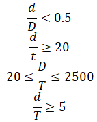
Where:
d - Nozzle OD
t - Nozzle thickness
D - Vessel OD
T - Vessel thickness
If any of application limits is violated, then nozzle considered as rigid
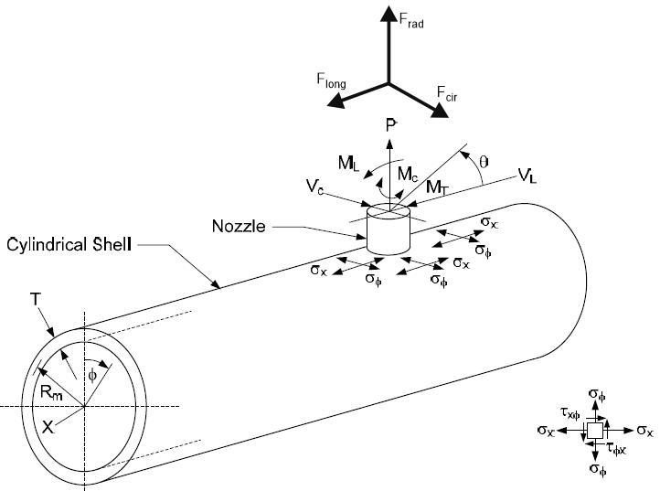
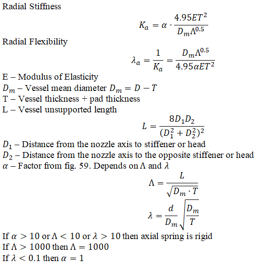
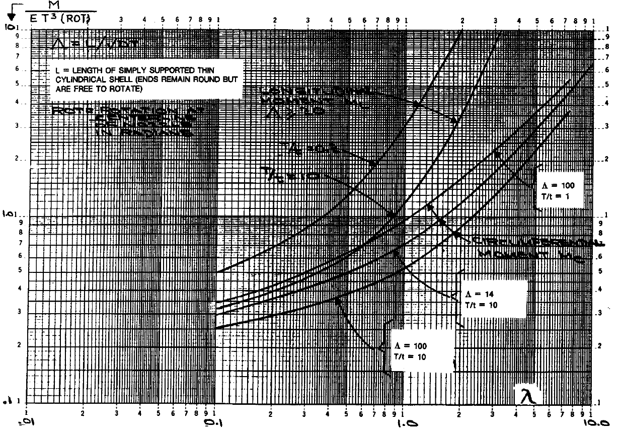
The figure 59 curves was assumed as polynomial of 10th degree and extrapolated up to alpha value 10.0. In this case interpolation between curves above alpha=10 limit is possible. But if alpha value become greater than 10, START-PROF will use rigid axial spring.
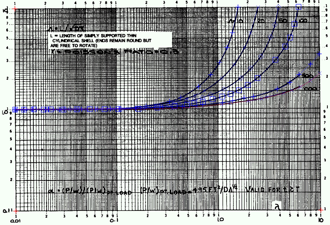
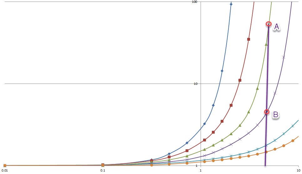
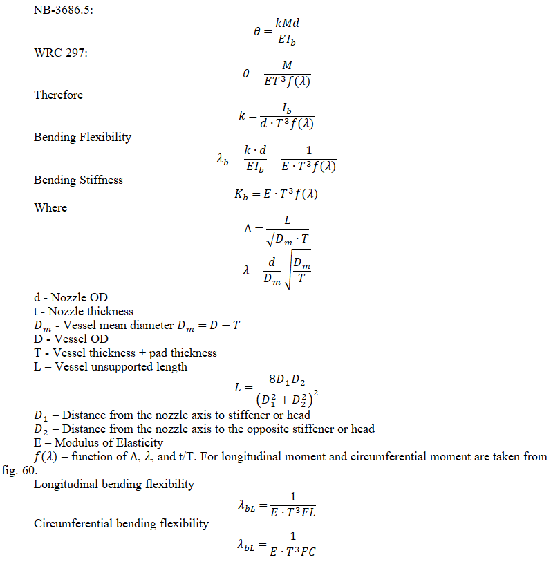
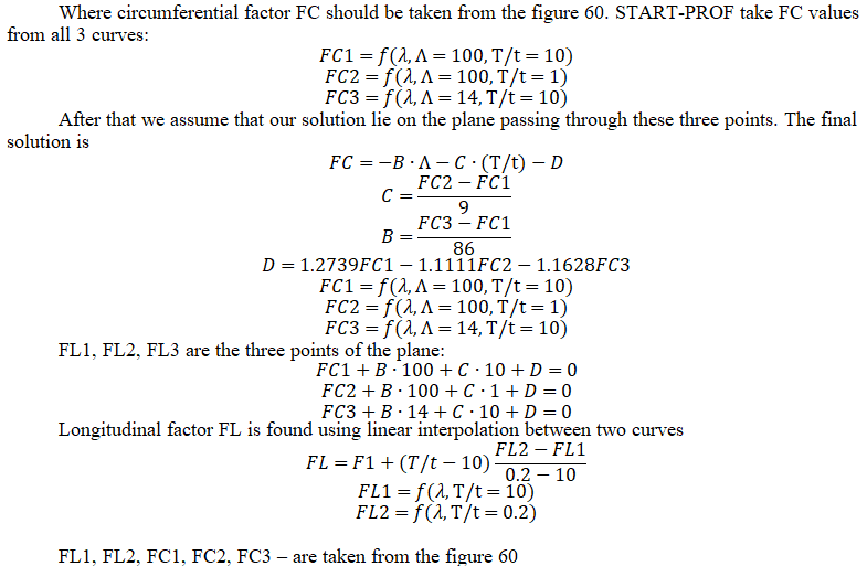

The inner part of nozzles is ignored during flexibility analysis. Nozzle junction to the spherical shell or head models are the same as those to elliptical heads. The following use limitations apply for nozzle junction stiffness (flexibility) analysis:
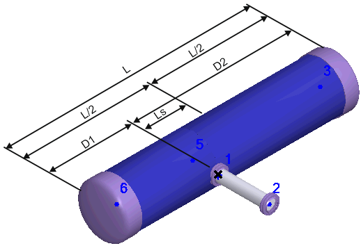
where s – vessel wall thickness, D – shell internal diameter, d – nozzle internal diameter, L – shell length, Ls – nozzle axis displacement relative to the middle of shell length.
Flexibility (stiffness) calculation of junction between nozzle and vessel is made in three directions:
 ;
; ;
; .
.The corresponding flexibilities are expressed as

Nozzle to shell restraints in the other three directions (linear along VL and perpendicular VC to the shell, rotational around the nozzle axis MT) are considered absolutely rigid.

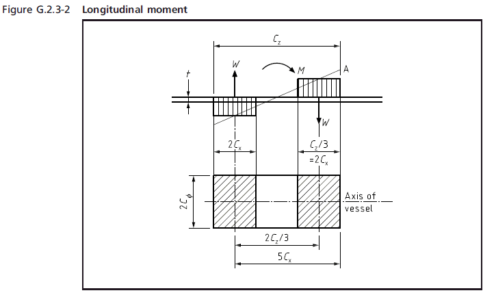

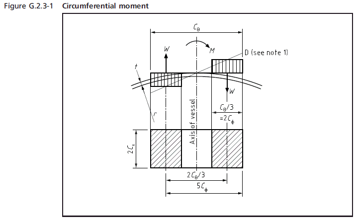
WRC 107/537 code provides a method to check the local stresses in cylindrical shell, spherical or elliptical head elements. But the method to check the local stresses in nozzle element is absent. For the thin wall nozzles we can miss overstress. In WRC 537 code all functions are digitized instead of represented in graphical form as in WRC 107. Formally it is the same code.
On the other hand, the WRC 297 code provides the method to check the local stresses in the nozzle-to-shell junction point. The method for head calculation is not provided.
Both WRC 107/537 and WRC 537 codes miss some important part and therefore complement each other. WRC 537 authors recommend to work with WRC 537 and 297 as a single document "WRC Bulletins 107 and 297 should be considered (and purchased) as an integral set. In addition, PVRC Technical Committees are working on a project that is envisioned to culminate in a new publication to add to the WRC Bulletin 107 and 297 set. The new publication will provide significant new technical information on local shell stresses from nozzles and attachments."
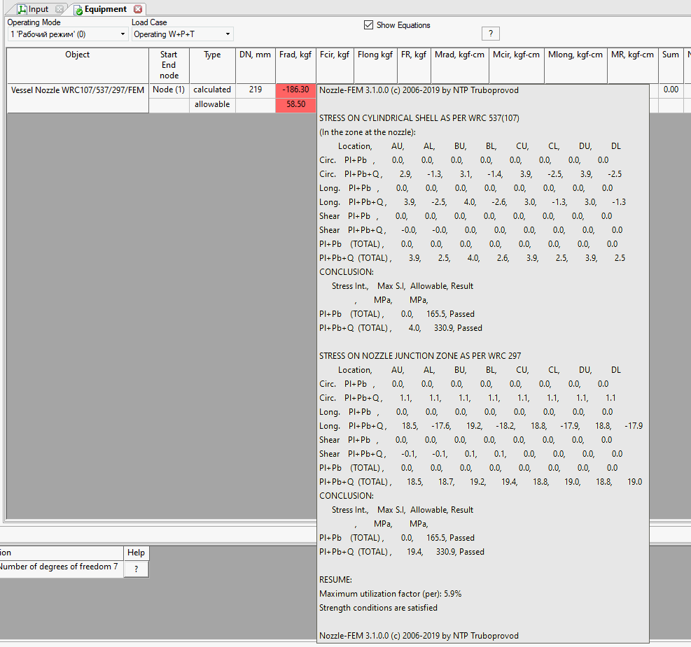
In START-PROF we check local stresses in cylindrical shell, spherical, and elliptical head using WRC 537 code. Also, we additionally checking the local stresses in the nozzle following the WRC 297 code. In this case we can be sure that we didn't miss anything important. Both Shell and Nozzle stresses are checked. We did not implement the cylindrical shell stress check according to WRC 297 code, because this method is different from WRC 107 code method and not so popular. We are offering users the optimal combination of calculation methods that can be used for all possible situations: cylindrical shell, spherical, or elliptical head. And check everything that is required: (a) Nozzle stress and (b) Shell stress / Spherical head stress / Elliptical head stress.
For details of stress calculation using WRC 537(107)/297 please refer to PASS/Nozzle-FEM Manual
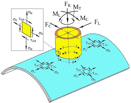
In the strength calculation of junction between branch pipes and cylindrical shells the following conditions shall be met:

In the strength calculation of junction between branch pipes and dished heads:

1. WRC 297 Local Stresses in Cylindrical Shells due to External Loadings on Nozzles – Supplement to WRC Bulletin №107
2. PD 5500: 2018 Specification for Unfired fusion welded pressure vessels
3. WRC 107 Local Stresses in Spherical and Cylindrical Shells due to External Loadings
4. WRC 537 Precision Equations and Enhanced diagrams for Local Stresses in Spherical and Cylindrical Shells due to External Loadings for implementation of WRC Bulletin 107