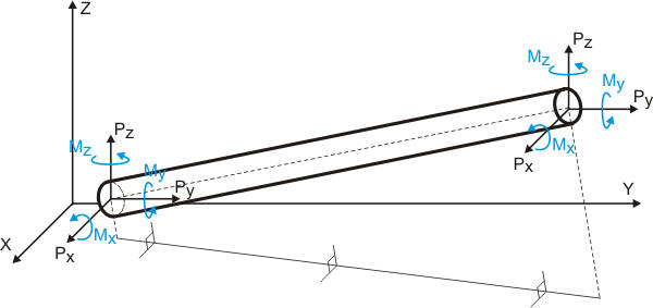
Forces corresponding with the coordinate axes direction are positive. Counter-clockwise moments (looking from the end of the axis on which the moment acts) are positive.
Forces can be displayed in the following ways (fig. 2):
no bends or valves are present in nodes M and N of element M-N (fig. 2.a). Forces are display for pipe cross-sections 1 and 2 adjoining nodes M and N from the side of nodes N and M, respectively.
valve is present in node N of element М-N (fig. 2.b). Forces in element М-N are displayed for pipe cross-sections 1 and 2. Cross-section 1 adjoins to node М from the side of node N, while cross-section 2 adjoins the valve from the side of node M.
bend is present in node N of element М-N (fig. 2.c). Forces in element М-N are displayed for pipe cross-sections 1 and 2. Cross-section 1 adjoins to node М from the side of node N, while cross-section 2 adjoins the bend from the side of node М.
for tees, forces in pipes adjoining the run are displayed for cross-sections 1 and 2 of node N (fig. 2.d), while in pipes adjoining the branch they are displayed for cross-section 3 of a symbolic node, placed at a distance of half the run diameter from node N.
A - automatically added nodes (invisible), B - dummy node, visible in 3D view
Fig. 2
Two force lines are always displayed for elements. Forces are not displayed for bends, since they are equal to force in adjoining pipe cross-sections.
Elements are ordered in the FORCES table in the order they were entered in input data.
Table view and contents depend on several properties, which must be input:
Property |
Description |
Operating Mode |
Choose operation mode for which the results will be displayed
Maximum - the maximum value will be displayed in every cell from all operation modes Here you can see analysis results from each of additional force-based loading, seismic, wind, and ice loading |
Submode |
For every operating mode software calculates several submodes (piping states)
For more information, see force and effect combination. |
Occasional Loads |
|
Show Effective Axial Force |
If internal forces table is used for nozzle or valve loads calculation, then thrust force P*Ac should be subtracted from axial load, where P - internal pressure, Ac=pi*(D-2t)^2/4 - cap area, D - outer nozzle diameter, t - nozzle wall thickness. Learn more about effective axial force. |
Coordinate system selection |
Forces and moments are displayed for the following coordinate axes:
Fig. 1. Internal forces in pipe element |
After analysis: Output > Internal Forces & Moments