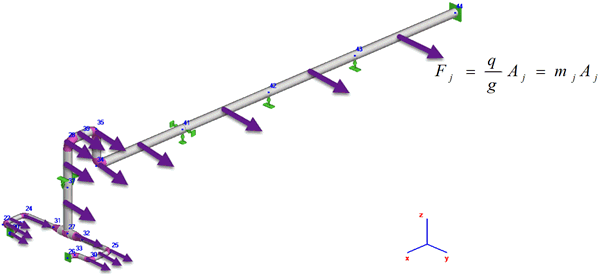

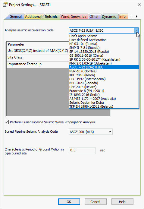
Available following codes for seismic loads:
User defined acceleration

ASCE 7-22 (USA), IBC
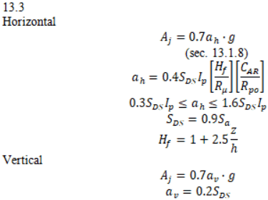
NSR-10 (Colombia)
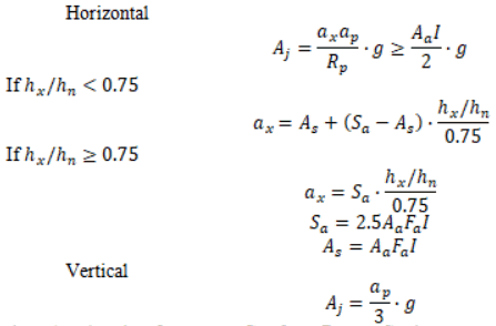
KBC 2016 (Korea)
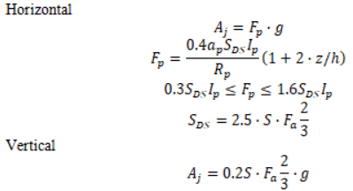
UBC 1997
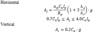
NBC 2020 (Canada)
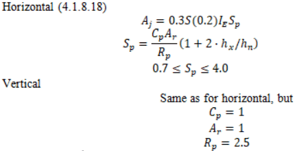
CFE 2015 (Mexico)


Eurocode 8 (EN 1998-1)
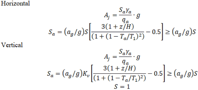
IS 1893-2016 (India)
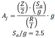
AS/NZS 1170.4-2007 (Australia/New Zealand)

Seismic Design Code for Dubai

TKP EN 1998-1 (Belarus)
NP 03-01
SNiP II-7-81
SP 14.13330.2018
GB 50011-2016 (China)
SP RK 2.03-30-2017* (Kazakhstan)
KMK 2.01.03-19 (Uzbekistan)
Property |
Description |
Horizontal Acceleration |
Horizontal seismic acceleration (+X, -X, +Y, -Y axes) in G's, 1G = 9.81 m/s2 |
Vertical Acceleration |
Vertical seismic acceleration (+Z, -Z axes) in G's, 1G = 9.81 m/s2 |
Static method correction factor, SF |
The value at which the static equivalent accelerations are multiplied. Recommended value 1.3 |
Site Class |
ASCE 7-22: Site class according to section 20 |
Importance Factor, Ip |
ASCE 7-22: Importance factor Ip sec. 13.1.3
NSR-10: A.2.5.2 KBC 2016: Section 306.10.1.4 |
Importance Factor, IE |
NBC 2020: Section 4.1.8.5 |
Pipe energy dissipation factor, Rp |
NSR-10: A.9.4.9 |
Aa |
NSR-10: Acceleration from map |
Component amplification factor, Ap |
NSR-10: Component amplification factor, Table A.9.6-1 KBC 2016: Table 306.10.2 |
Response factor, Rp |
KBC 2016: Table 306.10.1 NBC 2020: Table 4.1.8.18 |
Component amplification factor, Ar |
NBC 2020: Table 4.1.8.18 |
Component factor, Cp |
NBC 2020: Table 4.1.8.18 |
Te |
CFE 2015:First Mode Period of Piping System |
Ar0 |
CFE 2015:Peak ground acceleration for rock soil, cm/s2 |
Damping
ratio, |
CFE 2015: Damping ratio |
Importance factor, ga |
Eurocode 8 (EN 1998-1):
|
Behavior factor, qa |
Eurocode 8 (EN 1998-1):
|
Design Ground Acceleration, ag |
Eurocode 8 (EN 1998-1): Design Ground Acceleration in G's |
Region seismic activity |
Construction region seismicity (7, 8, 9 points on the MSK-64 scale map) |
Site seismic activity |
Construction site seismicity (6, 7, 8, 9, 10 points) |
Site soil category |
I, II, III. Table 1 SNIP II-7-81*, table 1 SP 14.13330.2018, appendix 1 NP-031-01 |
Vertical seismic acceleration factor Kv |
Equal to the correlation of maximum (peak) vertical soil acceleration and maximum (peal) horizontal soil acceleration. Set based on seismic microzoning data. In the absence of data, should be set as 0.7. More... |
Earthquake frequency |
Table 17 SNIP II-7-81*, table 16 SP 14.13330.2018 |
Piping seismic resistance category |
Is, IIs section 11.2.5 RD 10-249-98 |
K1 Factor |
0.125-1.0. Table 3 SNIP II-7-81*, table 5 SP 14.13330.2018. The following values are recommended:
|
Alpha1 |
Horizontal seismic influence coefficient per. 5.1.4 GB50011-2016 |
Perform buried pipeline seismic wave propagation analysis |
|
Buried pipeline seismic analysis code |
Choose the code that will be used for seismic axial strain value calculation |
Characteristic period of ground motion, Tg |
Characteristic period of ground motion. Used to calculate the seismic wave lengths. The default value is 0.5 s |
Dialog window opens automatically when creating a new analysis file or opening an existing analysis file. To open this window in an open file, use File > Project Settings>Seismic