

Read about START-PROF pipe stress analysis software
Above ground pipelines are subject to inertial forces caused by seismic accelerations of the basement. More information about the methodology for such a calculation can be found here.
But for underground (buried) pipelines, inertial forces are not decisive in the stress analysis, because the soil surrounding the pipe damps its own vibrations. Therefore, when calculating underground pipelines, the action of inertial forces is neglected.
The greatest influence on the stresses in the underground pipelines is exerted by deformations of the surrounding soil caused by the propagation of seismic tensile-compression, shear and Rayleigh waves. The photographs below show the effects of seismic waves.
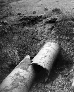
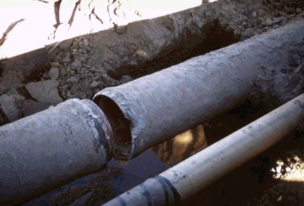
When a longitudinal wave passes, soil particles move along the direction of its propagation and cause axial deformation of the underground pipeline. With the passage of a shear wave, soil particles move across the direction of its propagation (in the vertical or horizontal plane) and cause bending deformations of the underground pipeline. Rayleigh waves occur when waves are reflected from the surface of the soil, and are similar to waves that occur on the surface of the water. Ground points in this case move in all directions. This type of wave is the most dangerous because it causes bending deformations of the underground pipeline more than when shear waves pass.
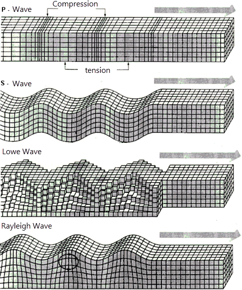
Character movement of ground points during the passage of longitudinal P-waves, shear S-waves, Love and Rayleigh waves
Longitudinal waves passing along the axis of the pipeline cause axial deformations:

where Vmax is the maximum velocity of horizontal ground vibrations, Vp is the longitudinal wave propagation velocity.
Shear waves passing along the axis of the pipeline cause the bending of the pipeline:

where Amax is the maximum acceleration of the soil, Vs is the shear wave propagation velocity.
Rayleigh waves passing along the axis of the pipeline cause bending and longitudinal deformation at the same time:

If a shear wave propagates at an angle to the axis of the pipeline, then it causes longitudinal deformations, which are equal to:

They reach their greatest value at an angle of 45 degrees:

The formulas for determining deformations from various waves depending on the angles of their propagation relative to the pipe section are collected in the table
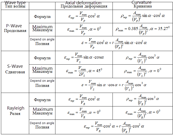
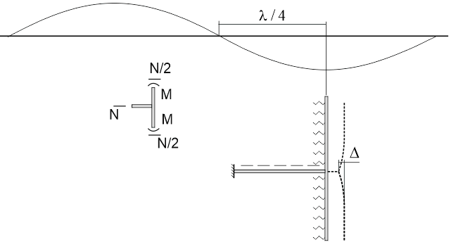
When calculating the piping system together with an array of surrounding soil to which deformations from the passage of seismic waves are specified. Values of deformations and stresses in the pipeline will depend on the geometry and rigidity of the entire structure, types of restraints, and mechanical properties of the surrounding soil. During the passage of seismic waves, the pipe completely follow the movements of the surrounding soil only until the force at the points of connection of the pipe and the soil does not exceed the friction forces. Below is a plot of soil movements during the passage of a longitudinal seismic wave and the direction of the friction forces acting on the pipeline
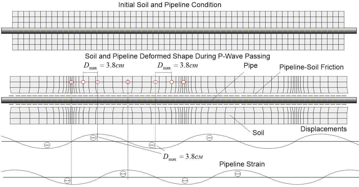
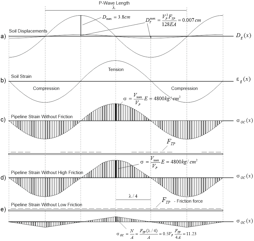
The figure below shows the diagrams of the distribution of axial stresses from the longitudinal force during the passage of the longitudinal P-wave along the pipeline.
a) function of the movement of soil points along the pipe
b) the deformation function at points of soil along the pipe
c) the distribution of axial stresses in the pipe in the absence of slippage of the pipe relative to the ground (infinite friction force)
d) the distribution of axial stresses with a large friction force and a large wavelength.
There are zones of pinch pipe in the ground, where slippage is absent. This pattern of stress distribution in the pipe is typical mainly for rocky soils.
d) the distribution of axial stresses when slipping along the entire length of the pipe. There are no zones of pinch pipe in the ground. The magnitude of the maximum stresses depends only by friction and wavelength. This pattern of stress distribution occurs in most cases.
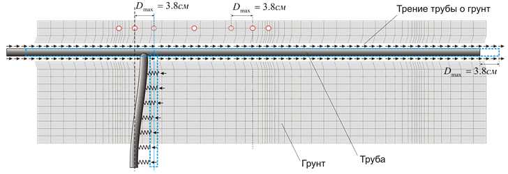
The greatest stresses arise at points where the mutual movement of the pipe and soil limit not only the friction forces, but also the structural elements of the pipeline. For example, bends, branches, anchors, etc. will prevent the mutual slippage of the pipe points and the soil points. Stresses near such points will be significantly larger and close to stresses calculated by the formula assuming the absence of slippage
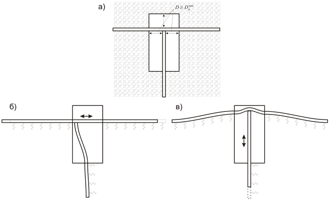
It is possible to reduce stresses in the pipeline and efforts in the branches only when special design decisions are made. For example, with the help of special wells with excavation in the places of branches, branches and any other devices that impede the longitudinal movement of the pipe relative to the ground. The design of such wells should provide unhindered longitudinal movement of the pipe relative to the ground, or the installation of flexible expansion cushions.
There are several codes that govern the stress analysis of pipelines for the propagation of seismic waves:
ASCE 2001 Guidelines for the Design of Buried Steel Pipe (American Lifelines Alliance)
GB 50032 (China)
GB 50470 (China)
SNiP 2.05.06-85 (Russia)
SP 36.13330.2012 (Russia)
GOST R 55989-2014 (Russia)
GOST R 55990-2014 (Russia)
SP 284.1325800.2016 (Russia)
SP 33.13330.2012 (Russia)
START-PROF uses the method of "equivalent thermal expansion" to calculate pipelines of arbitrary configuration for the propagation of seismic waves.
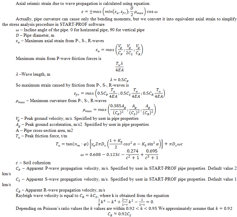
The equivalent relative strain of the pipeline is calculated using the following method, which is based on [9] and other papers [1]-[8], and improved by START-PROF authors. This strain is applied to the pipeline like an additional thermal expansion. This method take into account all 3 seismic wave types (P, S, R) instead of only P-wave in original ASCE 2001 (ALA) method
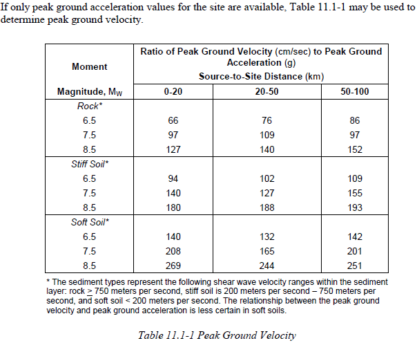
If only peak ground acceleration values are available, the following table may be used (according to ASCE 2001):
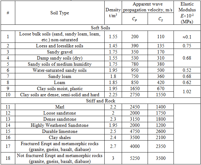
Recommended wave velocity values are shown in the table [12]:
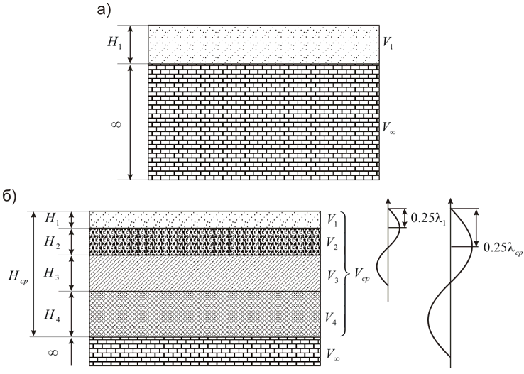
The apparent wave propagation speed should be specified not for the soil that we can see on the earth surface. This speed should be should be calculated using the following method, depending on soil layers thickness and wave speed values for each layer, see picture below.
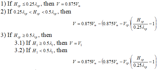

In the case of calculating a long straight restrained pipe, for example between two anchors, the resulting stresses will be exactly equal to the equation above. But in the case of calculating a pipeline of a more complex structure, with turns, branches, expansion loops, etc. - longitudinal stresses will be less, but additional bending stresses will also occur. Thus, using START-PROF it is possible to determine, for example, the necessary step and the distance between the U-shaped expansion loops needed to reduce the seismic stresses, arising during the passage of a longitudinal seismic wave.
To perform the calculation, in the Project Settings you need to enable the calculation option for the propagation of seismic waves. And in the additional properties of each pipe, set the parameters necessary for calculation of Sa. After analysis check results in stress table.
Two checks are performed.
First check according to ASCE 2001 (ALA):
Stresses are calculated from thermal expansions, weight, and seismic wave propagation effect. This check is made only for straight pipes. For tension 0.5% strain is allowed, and for compression buckling check is made.

Second check:
Stresses are calculated from thermal expansions, weight, and seismic wave propagation effect. This check is made for straight pipes and fittings. It is based on 4 times of Yield limit stress, that is equivalent to approximately 0.4% strain limit

F - Axial force thermal expansions, pressure Bourdon effect, weight, and seismic wave propagation effect
E - Elastic modulus
t - Pipe wall thickness
D - Pipe outside diameter
Sy - Yield Stress at operating temperature
Sh - Code Allowable Stress at operating temperature
To model the Landslide, Permanent Ground Deformation (Seismic Fault, etc.) or other soil movements, add soil movements in the buried pipe properties. Learn more information here
1. ASCE 2001 Guidelines for the Design of Buried Steel Pipe (American Lifelines Alliance), 11.1
2. ASCE 4-98 Seismic Analysis of Safety-Related Nuclear Structures and Commentary, 3.5.2
3. ASCE Guidelines for the seismic design of oil and gas pipeline systems, ch.6
4. ASCE Structural Design and Analysis of Nuclear Plant Facilities, 7.6.2
5. BNL-52361 Seismic design and evaluation guidelines for the department of energy high-level waste storage tanks and appurtenances, 1995, ch. 7
6. American Lifelines Alliance Seismic guidelines for water pipelines, 2005
7. M.J. O'Rourke, X. Liu Response of buried pipelines subject to earthquake effects, 1999
8. Савинов О.А. Сейсмостойкость магистральных трубопроводов и специальных сооружений нефтяной и газовой промышленности, 1980 (Russian language)
9. Бирбраер А.Н. Расчет конструкции иа сейсмостойкость, 1998 (Russian language)
10. СНиП 2.05.06-85 (Russian language)
11. GB 50032 (Chinese language)
12. Методические рекомендации по определению динамических свойств грунтов, скальных пород и местных строительных материалов. П01-72. // ВНИИГ им. Б.Е. Веденеева, 1972 (Russian language)