Links:
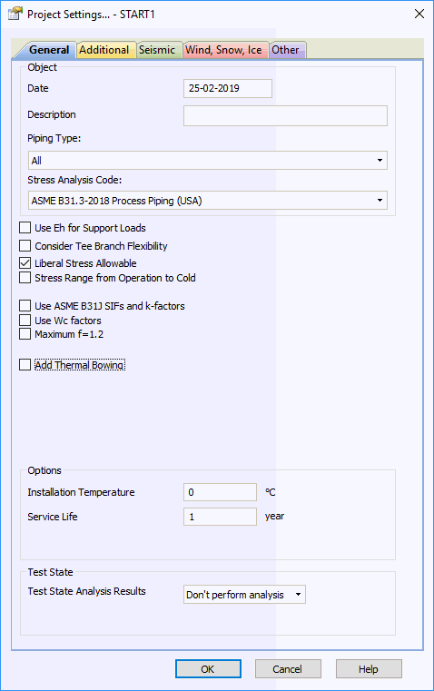
General project properties for the analysis are input in this window

Property |
Description |
Date |
Any text |
Object number |
Any text |
Stress analysis code |
Code used for stress analysis and analysis mode (see "stress analysis code" table). You can't change the code while the project file is already open. To change the code need to close the project file, open it again and change the code |
Use Eh for support loads |
By default, START-PROF use cold Elastic modulus for pipe and fitting stiffness calculation in all load cases for ASME codes. If this option is checked then START-PROF use hot Elastic modulus for load cases used for support and vessel load calculation. Using this option can reduce the loads on supports and nozzles, pumps etc. More... We recommend to switch on this option |
Consider creep effect |
If this option checked, 2 additional load cases considering creep effect in operating and cold mode will be added and add two additional sustained stress checks in operating mode and in cold mode. The creep stress relaxation in operating mode and pipe self-springing effect in cold state is taken into account. More... We recommend to switch on this option
|
Consider tee branch flexibility |
If this option is checked, the branch flexibility will be considered for all tees with Db/Dh less than 0.5 (Db - branch diameter, Dh - header diameter). Flexibility calculated according to ASME BPV SIII div 1 class 1 NB 3686. This option affect all types of tees including non-standard. More...
|
Liberal Stress Allowable |
For example for ASME B31.3 code:
The same idea is used for all other codes |
Stress range from operation to cold |
By default START-PROF calculate the stress range between operation and installation state. If this option is checked, then START-PROF calculate the stress range between operation and cold mode. In this case the stress range could be greater. . We recommend to switch on this option Installation mode is state before the piping first warming up. The cold mode is a state after piping cooling down. The difference is in friction forces behavior. In installation state all friction forces is zero. In cold mode all friction forces is not zero and their direction is opposite to the direction of friction forces in operating mode.
|
Add axial force and torsion stress |
By default, the most of ASME, EN, GB, DLT codes (except ASME B31.3) doesn't consider axial force and torsion moment influence on sustained and expansion stress. For example: ASME B31.1 : ISO 14692:
It's not safe in some situations. For example in case of pipe restrained between two fixed anchors the code stress will be always zero. But in real life this pipe may collapse.
If this option is checked, START-PROF add axial force (F/A) and torsion moment (Mt/2Z) stress to sustained and expansion stress check. For example ASME B31.1 equations will be following:
ISO 14692:
It adds more safety to standard code stress checks. We recommend to switch this option on. More... |
Use code SIFs and k-factors Use ASME B31J SIFs and k-factors Use FEM SIFs and k-factors |
If first option is selected, then PASS/START-PROF calculate SIF and k according to the selected code equations. If second option is selected, then SIF and k calculated according to the ASME B31J equations. If third option is selected then SIF and k factors calculated using finite element method (using integration with PASS/NOZZLE-FEM). |
Use Wc factors |
If selected, then allowable stress for sustained loads is multiplied by circumferential weld joint efficiency factor Wc for ASME B31.1, ASME B31.3, DL/T 5366. More... |
Maximum f=1.2 |
See ASME B31.3 302.3.5 equation (1с). If selected, then maximum value of stress range factor f can be 1.2 for materials with enabled option "Maximum f=1.2" in material database, otherwise maximum value always f=1.0 |
Maximum f=1.0 |
See ASME B31.4 403.3.2. If selected, then maximum value of stress range factor f can be 1.0, otherwise maximum f=1.2 |
Use In-Plane/Out-Plane SIF |
If selected, then used table H.3 of EN 13480, else used table H1. See 12.3.8 EN 13480 |
Liberal Stress Allowable |
If selected, then equation 11.6-5 EN 13480 is used, otherwise equation 11.6-4 is used |
Consider Corrosion |
If selected, corrosion allowance is subtracted from the wall thickness according to 12.3.1 EN 13480 |
With Surveillance of Creep Exhaustion |
If selected, then right two columns of table 5.3.2-1 EN 13480 are used |
Use maximum distortion energy |
True - used maximum distortion energy equation False - used maximum shear stress equation (Tresca combined stress) Maximum - used maximum value of Tresca combined stress and maximum distortion energy equation See. 402.7 ASME B31.4 and A842.2.2 (c) ASME B31.8 |
Restrained/Unrestrained |
Detailed information on Restrained and Unrestrained pipe sections of buried pipe can be found here. Specify manually - user should manually specify restrained or unrestrained option for each buried pipe element in the model Autodetect - start automatically select "restrained" or "unrestrained" option. See details here. Use START Smart Check - use alternative (non code!) strength check equations suggested by START-PROF authors that can guarantee the strength for booth restrained and unrestrained pipelines. See details here. |
Add Thermal Bowing |
Consider affect of thermal bowing on horizontal pipes. More... |
Use MDMT Allowable Reduction |
Take into account the minimum impact test exemption temperature reduction according to 323.2.2 (c) ASME B31.3. Read more...
|
High pressure |
All piping considered as high pressure according to GOST 32388-2013 if checked. If not checked then only the elements with design pressure higher than 10 MPa considered as high pressure |
Overload factor |
This factor should be entered for high temperature pipelines according to p. 8.1.15 GOST 32388-2013, RD 10-249-98 section 5.2.6.2.4. |
Ambient temperature |
Average wall (metal) temperature at the time when pipe segments become a single joined structure. More... This property can be changed in
different operation modes.
To see the value of this property in all operating modes push
the |
Service life |
Service life can be from 1 to 50 years or from 10000 to 300000 hours (for RD 10-249-98). 1 year is considered to be equal to 365*24 hours. Used for fatigue strength analysis, as well as for determining nominal allowable stress from the materials database (for RD 10-249-98). |
Test state analysis |
Product with which tests are done (water, gas). Test state analysis need not be run. Product weight is taken into account for determining loads on equipment, expansion joint deformations, displacement, and Stress. Wall thickness analysis for test pressure Ptest (set in element properties) is done. |
Test temperature, Тtest |
Operation temperature in test state. Average wall (metal) temperature along the piping during testing. Testing is usually done without product heating, i.e. at surrounding air temperature. Usually set as Тtest = +200С. |

Property |
Description |
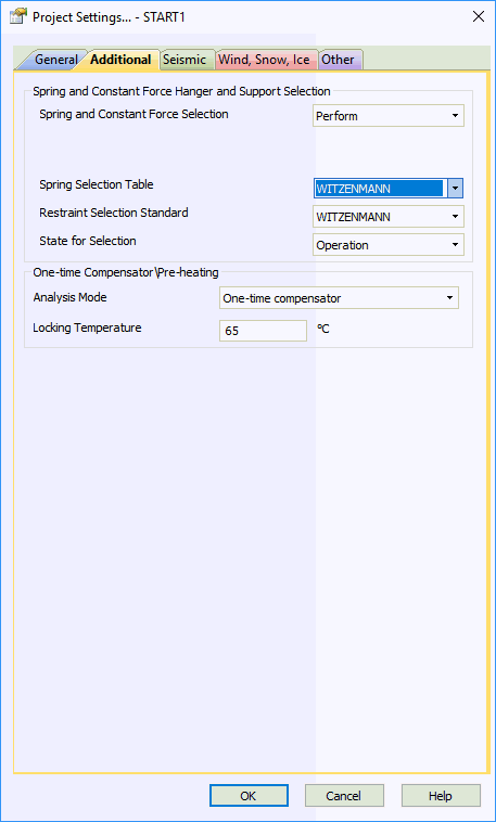
Spring selection |
Selected if variable spring supports are present. If "run" is selected, automatic variable spring support selection is done and their compression force is calculated according to RTM 24.038.12-72. Code for springs must be input |
Spring selection table |
Code of standards for springs from the springs database used for their selection. If "other" is selected, allowable load and stiffness must be specified in spring properties |
Constant force hanger and support selection |
Used if constant spring supports are present. If "run" is selected, automatic selection of constant spring supports and hangers is done. Standard for these supports must be specified. If "other" is chosen, then program will show the load and displacement for manual constant load spring selection for any manufacturer |
Restraint selection standard |
Constant force restraints code from the constant force restraints database |
Spring and constant spring support selection state |
Spring flexibility can be selected from zero displacement from weight load conditions in operation or cold state. Spring selection in cold mode is for advanced users, who understand the advantages of this method. With selection in cold mode, installation must be done with the "separation method", where support adjustments are less time-consuming than the traditional method. In other cases, selection in operation state is recommended. More... |
Analysis mode |
There are two options: Single Use Compensator analysis or pre-heating analysis To use the single use compensator or pre-heating, please switch the "Spec. Analyze" flag in the operation mode editor |
Locking temperature, Тweld |
Piping locking temperature at which single use compensators are welded. Optimal locking temperature is half of temperature range Тweld = (Тop - Тassembly) / 2. |
Pre-heating temperature, Тweld |
Piping pre-heating temperature at which the trench is backfilled. Optimal pre-heating temperature is half of temperature range Тweld = (Тop - Тassembly) / 2. |

Property |
Description |
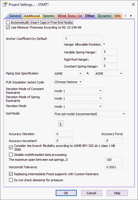
Automatically insert cap in free nodes |
After starting analysis, all end nodes will be considered capped |
Recalculation of elevation above a ground surface |
If this option is on, then the elevation above the ground surface for wind and ice load calculation is calculated automatically assuming that the ground surface is horizontal. This option should be switched off for pipelines laying on the ground surface with variable heights |
Use minimum thickness |
During wall thickness analysis, a value no less than that allowed in standards is given:
If the flag is not checked, minimum wall thickness check for GOST 32569-2013 is not done. For other standards, it is done regardless. |
Anchor coefficient by default |
Default load factor. From 0.5 to 1.0. Used for intermediate supports load analysis. |
Pipping size specification |
Specifies the piping and component specification standard filter for databases: All (all available standards), ASME (American National Standard), GOST (Russian), EN (European Union) |
R |
Specifies the bend radius specification standard: ASME (American National Standard), GOST (Russian), EN (European Union) |
PUR Insulation Jacket Code |
Select the PUR pre-insulated pipe manufacturer |
Anchor coefficient by default |
Allowable rotation for various type of hangers. When exceeded, the warning message appears |
Number of cycles |
Minimum number of cycles used in EN 13941 calculations |
Iteration mode |
Pre-defined iteration algorithm selection for non-linear problems with friction and single-directional restraints. Switched in cases of problems with iteration convergence
Please note that nonlinear systems with friction, single-directional restraints and gaps may have a many equilibrium states (solutions). And it all are correct. For example, a cubic equation has three solutions. And all three solutions are correct. Therefore, it is quite possible that different types of iterations will converge to the different solutions for the same system. Different support loads, displacements and stresses can be obtained. This is a normal situation, because we do not take into account the history and load application sequence, but trying to find the system equilibrium state right from the installation state. |
Distance between markers |
The maximum distance for automatic placement of hidden markers to improve the accuracy of displacement calculation. Default value is 150 |
Number of iterations |
Maximum number of iterations. Default value is 1000. If maximum value is achieved, then iterations stop and offered the analysis results for the last iteration. If iterations are not converged, you may increase the number of iterations up to 2000. If still no convergence usually it means that it is impossible to achieve convergence due to cyclic opening and closing of the gaps and single-directional restraints. It is recommended to change the model, remove friction, etc. (see description of error E828) |
Number of iterations of main system |
Maximum number of iterations when gap state (open/closed) is changed and single-directional support state (on/off) is changed. It is recommended to use default value 50 |
*Iteration mode of constant restraints |
Constant spring support selection algorithm type |
*Iteration mode of spring restraints |
Mode 1 - At LH2 load case single-directional links on/off mode are calculated by iteration, mode 2 - single-directional links are always on |
*Soil model |
|
*Consider tee branch flexibility |
Consider tee branch flexibility
for Russian codes: |
*Accuracy iteration, tf |
Parameter has an influence on the iteration process. It is the accuracy of the force in wrong direction. If force is higher than this value the restraint is switched off. if force is lower then restraint is not switched off. It stabilize the iteration process with single-directional links. If the parameter is 0 then the default value 0.001 tf is used |
*Accuracy movement |
Parameter used for accuracy control after analysis. The error is generated if the displacement along the restricted direction is greater than wall thickness multiplied by this parameter. If the parameter is 0 then the default value 0.15 is used (i.e. movement is greater than 15% of the wall thickness) |
*Accuracy force |
Parameter used for accuracy control after analysis. The error is generated if the load along the restricted direction is greater than the maximum vertical load multiplied by this parameter. If the parameter is 0 then the default value 0.02 is used (i.e. load is greater than 2% of the maximum vertical load) |
*The maximum span between soil springs, D |
The maximum span between soil springs in restrained zone. Default value is 100D |
*Horizontal Tolerance |
Specifies the maximum slope of a straight pipe. The pipe pitch is calculated using formula: |DZ| / ( DX^2 + DY^2 + DZ^2 )^0.5. Used for
|
* |
Hidden property. It should be edited only by professionals at their own risk! |
Dialog window opens automatically when creating a new analysis file or opening an existing analysis file. To open this window in an open file, use File > Project Settings