
This table displays linear and rotational expansion joint deformation as projections on coordinate axes. Linear deformation is mutual pipe end displacement, while rotational deformation is mutual rotation of pipe ends. Deformation sign depends on the direction of local axes of elements adjoining the expansion joint.
For universal expansion joints the relative displacements of flexible joint (deformations) are checked using the following summary equation:
If allowable torsion rotation available, then 4th member is added to the equation above
For axial expansion joint the summary calculated as equivalent axial deformation x divided by allowable axial deformation xa:
Lb – Corrugated length of bellows
Lu – Distance between outermost ends of convolutions
Dm – Mean diameter of bellows convolutions
For single use compensators, deformation values for the welding moment are displayed (at welding temperature input in Project Settings).
Table view and contents depend on two properties, which must be input:
Property |
Description |
Operating Mode |
Choose operation mode for which the results will be displayed
Maximum - the maximum value will be displayed in every cell from all operation modes Here you can see analysis results from each of additional force-based loading, seismic, wind, and ice loading |
Design state selection |
For every operating mode software calculates several submodes (piping states)
For more information, see force and effect combination. |
Occasional Loads |
|
Axis |
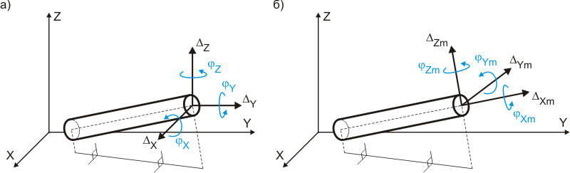
Linear and rotational expansion joint deformation is displayed as projections on coordinate axes:
Fig. 1. Expansion joint deformation in global (general) and local coordinate systems |
| Note | Description |
Expansion joint skew exceeds allowed |
Expansion
joint skew conditions not met |
Deformation exceeds axial expansion |
Condition
|
Deformation exceeds rotational expansion |
Actual rotational deformation exceeds allowable rotational expansion. Piping model or expansion joint properties must be changed. |
Deformation exceeds lateral expansion |
Actual lateral deformation exceeds allowable lateral expansion. Piping model or expansion joint properties must be changed. |
After analysis: Output > Expansion Joint Deformations
 .
. 