

The piping stress table gives results for the states required by the selected code.
Stress tables are different depending on the code selected in Project Settings and analysis mode:
Stress from seismic wave propagation effect are described here
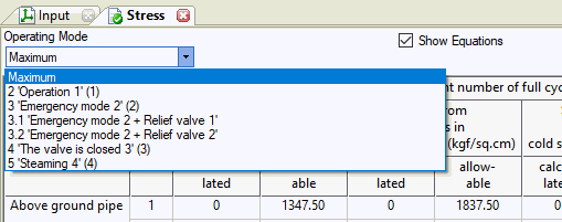
You can see stresses only for specific operation mode or maximum stress from all operation modes. If you choose "Maximum' then for every table cell maximum stresses and corresponding allowable stresses are shown from operating mode with the greatest ratio of design stress divided by allowable stress.
Stress is calculated for straight pipes (at the start and end of each element), bends (at the start and end) and tees (in three cross-sections). See the "internal forces in piping elements" section. For a more accurate analysis, long buried sections (with the length of more than 150 times the diameter) should be divided by inserting intermediate nodes. It is also recommended to insert intermediate nodes in the middle of the gap between supports for above-ground pipelines, for a more accurate calculation of stress.
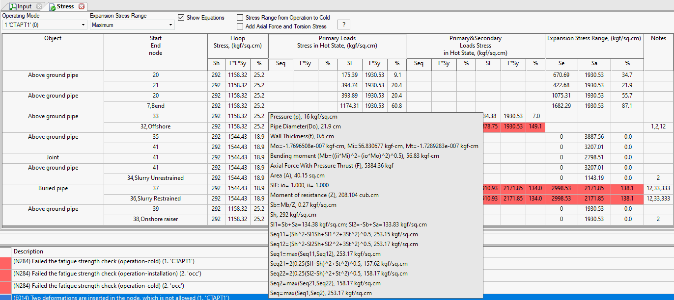
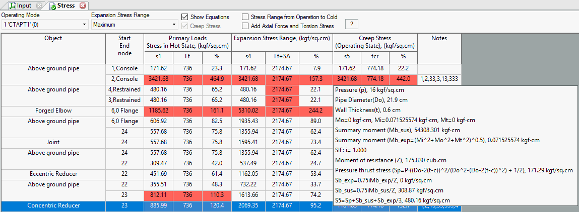
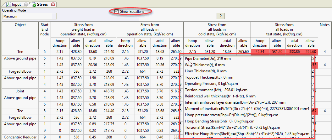
If option "Show Equations" is checked then if you put the mouse cursor over the table cell, popup message appears with all the equations used while calculating value in the table cell. You can use CTRL+C button combination to copy this text into clipboard.
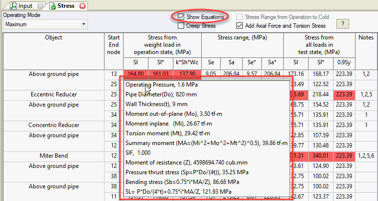
If strength conditions are not met, the corresponding cell will be highlighted in red, and in the last table column an error code is displayed, the text of which can be read by hovering over it with the cursor (see fig. below). When printed, the error and warning messages can be found below the table. If strength conditions are met, the "notes" column remains empty.
Primary Loads. Primary loads are force driven: weight, pressure, spring, etc. Primary loads are not self-limiting. Once plastic deformation begins it continues unabated until force equilibrium is achieved. Excessive primary load causes gross plastic deformation and rupture. Failure may occur with a single application of the load.
Secondary Loads and Expansion stress. Secondary loads are displacement driven: thermal expansion, anchor movements, settlement, etc. Secondary loads are self-limiting, i.e. the loads tend to dissipate as the system deforms through yielding or deflection. Secondary loads are typically cyclic in nature (except settlement). Allowable limits for secondary stresses are based upon cyclic and fatigue failure modes, and are therefore limited based upon requirements for elastic cycling after shakedown and the material fatigue curve. A single application of the load never produces failure. Rather catastrophic failure can occur after some (usually high) number of applications of the load. Therefore, even if a system has been running successfully for many years, it is no evidence that the system has been properly designed for secondary loads.
Stresses calculation depends on options:
"High Temperature" in Operation Mode Editor
"Stress range from operation to cold" in Project Settings
"Use Wc factors" is turned on in Project Settings
Corrosion allowance and mill tolerance doesn't affect stresses in this code
Button |
Property |
Description |
|
Stress due to sustained or occasional loads, Sl |
A - cross-section area, F - axial force, Mi - in-plane moment, Mo - out-plane moment, Mt - torsion moment, Z - moment of resistance L1 - sustained loads (W+P), L6 - operational loads (W+P+T), L11 - operational loads + occasional force-based loads (W+P+T+OCC) |
Allowable stress from sustained or occasional loads |
ASME B31.1 Sustained:
ASME B31.1 Occasional:
ASME B31.9 Sustained:
ASME B31.9 Occasional:
k - occasional k-factor Sh - hot allowable stress from material database Wc - Circumferential weld strength reduction factor from material database. Added if option "Use Wc factors" is turned on in Project Settings E - Weld Joint Efficiency Factor |
|
|
Stress range from between operation and (installation/cold) state, Se |
Stress range calculated between operation and installation mode. If option "stress range from operation to cold" is on, then between operation and cold mode.
For ASME B31.1 buried piping additional check for straight pipes is done according to VII-4.5, VII-5:
|
Allowable stress range, Sa |
N - number of full cycles. Calculated by:
Information for calculation is got from temperature cycles For buried straight pipes allowable stress is:
|
|
|
Stress due to sustained in test state, Sl |
The same as stress due to sustained or occasional loads, Sl |
Allowable stress from sustained loads in test state |
|
|
|
Creep stress from sustained and displacement loads in operating mode |
Checked only if "Consider creep effect" in Project Settings is switched on Calculated the same as Sl and Sl*. But the temperature difference is multiplied by "creep diminish factor" from pipe properties |
Allowable stress |
Sh - hot allowable stress |
|
|
Creep stress from sustained and displacement loads in cold mode |
Checked only if "Consider creep effect" in Project Settings is switched on Calculated the same as Sl. But the temperature difference is multiplied by "creep self-springing factor" from pipe properties |
Allowable stress |
1.5Sc - cold allowable stress |

Stresses calculation depends on options:
"High Temperature" in Operation Mode Editor
"Stress range from operation to cold" in Project Settings
"Use Wc factors" is turned on in Project Settings
Maximum f always 1.0 in Project Settings
High Pressure Piping in Pipe Properties
During sustained stress calculation, the crossection area A and modulus of resistance Z wall thickness is reduced by corrosion allowance.
During sustained stress calculation, the crossection area A and modulus of resistance Z wall thickness is not reduced.
Button |
Property |
Description |
|
Stress due to sustained or occasional loads, Sl |
Occasional stress:
A - cross-section area, F - axial force, Mi - in-plane moment, Mo - out-plane moment, Mt - torsion moment, Z - moment of resistance L1 - sustained loads (W+P), L6 - operational loads (W+P+T), L11 - operational loads + occasional force-based loads (W+P+T+OCC) There are 2 types of sustained stresses in the ASME B31.3 code: Sl_Alt, Sl_Std Sl_Std - Sustained stress in cold state (W+P). The single-directional restraints and gap (working/not working) states are calculated. In most cases all resting supports are working in this state Sl_Alt - Sustained stress in hot state (W+P). The single-directional restraints, gap (working/not working) configuration used the same as in operation state (W+P+T). Some resting supports may be switched off, because they are lifted off in hot state If no supports are lift off in hot mode (W+P+T), then Sl_CLD and Sl_HOT are equal. |
Allowable stress from sustained or occasional loads |
Sustained:
Occasional:
k - occasional k-factor Sh - hot allowable stress from material database Sy - Yield stress from material database Wc - Circumferential weld strength reduction factor from material database. Added if option "Use Wc factors" is turned on in Project Settings |
|
|
Stress range from between operation and (installation/cold) state, Se |
Stress range calculated between operation and installation mode. If option "stress range from operation to cold" is on, then between operation and cold mode.
|
Allowable stress range, Sa |
N - number of full cycles. Calculated by:
Information for calculation is got from temperature cycles |
|
|
Stress due to sustained in test state, Sl |
The same as stress due to sustained or occasional loads, Sl |
Allowable stress from sustained loads in test state |
|
|
|
Creep stress from sustained and displacement loads in operating mode |
Checked only if "Consider creep effect" in Project Settings is switched on Calculated the same as Sl. But the temperature difference is multiplied by "creep diminish factor" from pipe properties |
Allowable stress |
Sh - hot allowable stress |
|
|
Creep stress from sustained and displacement loads in cold mode |
Checked only if "Consider creep effect" in Project Settings is switched on Calculated the same as Sl. But the temperature difference is multiplied by "creep self-springing factor" from pipe properties |
Allowable stress |
1.5Sc - cold allowable stress |
|
|
Creep-Rupture Usage Factor, u |
Creep-Rupture Usage Factor, u according to ASME B31.3-2018, V303.2
|
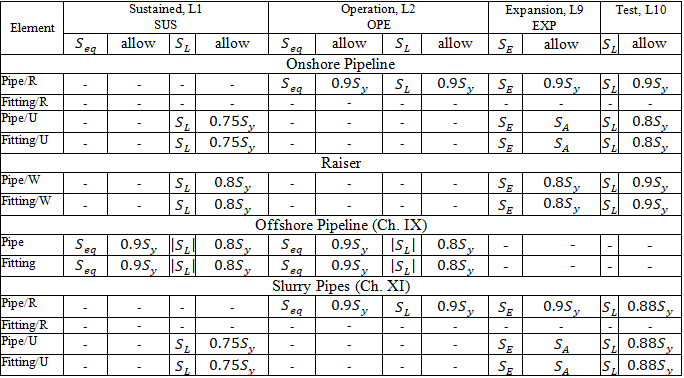
Stresses calculation depends on options:
"Add axial force and torsion stress" in Project Settings
"Stress range from operation to cold" in Project Settings
Use maximum distortion energy theory=True/False/Maximum in Project Settings
Restrained/Unrestrained: Specify manually, Autodetect, Use START Smart Check in Project Settings
Pipeline location: Onshore Pipeline, Slurry Pipes, Offshore Pipeline in Pipe Properties
Pipeline type: Restrained, Unrestrained, Riser and Platform for Inland Waterways in Pipe Properties
Corrosion allowance doesn't affect stresses in this code
Sustained, Operation, Expansion, Test stresses:
Start smart check:
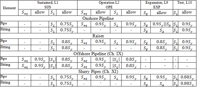
Stresses from occasional loads:
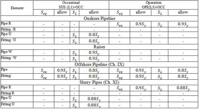
Start smart check from occasional loads:
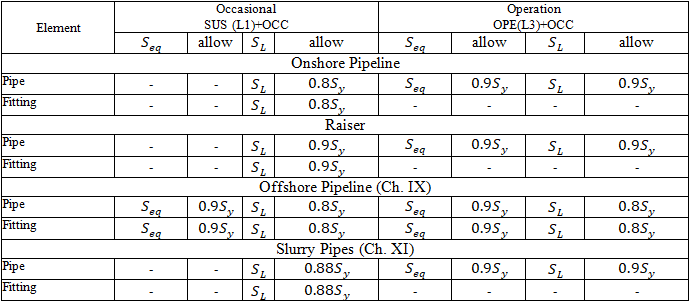
Button |
Property |
Description |
|
Hoop Stress |
|
|
Stress due to sustained or occasional loads, Sl |
Onshore Pipeline, Slurry Pipes (Ch. XI), Riser and Platform for Inland Waterways: Restrained: Not checked Unrestrained:
From occasional force-based loads:
F - axial force without Bourdon effect Start Smart Check:
From occasional force-based loads:
F - axial force with Bourdon effect Offshore (Ch. IX):
A - cross-section area, Mi - in-plane moment, Mo - out-plane moment, Mt - torsion moment, Z - moment of resistance L1 - sustained loads (W+P), L6 - operational loads (W+P+T), L11 - operational loads + occasional force-based loads (W+P+T+OCC) |
Allowable stress from sustained or occasional loads |
Onshore Pipeline:
Occasional:
Slurry Pipes:
Occasional:
Riser and Platform for Inland Waterways:
Occasional:
Offshore (Ch. IX)
Sy - Yield Stress from material database |
|
|
Stress due to operation loads, Sl |
Onshore Pipeline, Slurry Pipes (Ch. XI): Restrained:
F - axial force without Bourdon effect Unrestrained: Not checked Start Smart Check:
F - axial force with Bourdon effect Offshore (Ch. IX): Same as for sustained loads |
Allowable stress from sustained or occasional loads |
Sy - Yield Stress from material database |
|
|
Stress range from between operation and (installation/cold) state, Se |
Onshore Pipeline, Slurry Pipes (Ch. XI), Riser and Platform for Inland Waterways: Restrained:
Unrestrained:
F - axial force without Bourdon effect Start Smart Check:
F - axial force with Bourdon effect |
Allowable stress range, Sa, Sa* |
Restrained:
Unrestrained:
Riser and Platform for Inland Waterways:
N - number of full cycles. Calculated by:
Information for calculation is got from temperature cycles |
|
|
Stress due to sustained in test state, Sl |
Restrained:
F - axial force without Bourdon effect Unrestrained:
F - axial force without Bourdon effect Start Smart Check:
F - axial force with Bourdon effect |
Allowable stress from sustained loads in test state |
Restrained:
Unrestrained: Onshore Pipeline:
Slurry Pipes:
Riser and Platform for Inland Waterways:
Offshore (Ch. IX) Not checked |
Stresses calculation depends on options:
"Add axial force and torsion stress" in Project Settings
"Stress range from operation to cold" in Project Settings
During sustained stress calculation, the cross-section area A and modulus of resistance Z wall thickness is reduced by corrosion allowance.
During sustained stress calculation, the cross-section area A and modulus of resistance Z wall thickness is not reduced.
Button |
Property |
Description |
|
Stress due to sustained or occasional loads, Sl, Sl* |
If "add axial force and torsion stress" off (Sl):
Occasional:
If "add axial force and torsion stress" on (Sl*):
A - cross-section area, F - axial force, Mi - in-plane moment, Mo - out-plane moment, Mt - torsion moment, Z - moment of resistance L1 - sustained loads (W+P), L6 - operational loads (W+P+T), L11 - operational loads + occasional force-based loads (W+P+T+OCC) |
Allowable stress from sustained or occasional loads |
Sustained:
Occasional:
k - occasional k-factor Sh - hot allowable stress from material database E - Weld Joint Efficiency Factor |
|
|
Stress range from between operation and (installation/cold) state, Se, Se* |
Stress range calculated between operation and installation mode. If option "stress range from operation to cold" is on, then between operation and cold mode. If "add axial force and torsion stress" off (Se):
If "add axial force and torsion stress" on (Se*):
|
Allowable stress range, Sa, Sa* |
N - number of full cycles. Calculated by:
Information for calculation is got from temperature cycles |

Stresses calculation depends on options:
"Add axial force and torsion stress" in Project Settings
"Stress range from operation to cold" in Project Settings
Use maximum distortion energy theory=True/False/Maximum in Project Settings
Restrained/Unrestrained: Specify manually, Autodetect, Use START Smart Check in Project Settings
Pipeline location: Onshore Pipeline, Offshore Pipeline in Pipe Properties
Pipeline type: Restrained, Unrestrained, Raiser and Platform Piping in Pipe Properties
Corrosion allowance and mill tolerance doesn't affect stresses in this code for all types of pipelines except risers.
For risers during stress calculation, the crossection area A and modulus of resistance Z wall thickness is reduced by corrosion allowance and mill tolerance.
Sustained, Operation, Expansion, Test stresses:

Start smart check:

Stresses from occasional loads:

Start smart check from occasional loads:

Button |
Property |
Description |
Hoop Stress |
|
|
|
Stress due to sustained or occasional loads, Sl |
Onshore Pipeline: Restrained: Not checked Unrestrained:
From occasional force-based loads:
F - axial force without Bourdon effect Start Smart Check:
From occasional force-based loads:
F - axial force with Bourdon effect Offshore (Ch. VIII ):
A - cross-section area, Mi - in-plane moment, Mo - out-plane moment, Mt - torsion moment, Z - moment of resistance L1 - sustained loads (W+P), L6 - operational loads (W+P+T), L11 - operational loads + occasional force-based loads (W+P+T+OCC) |
Allowable stress from sustained or occasional loads |
Onshore Pipeline: Restrained:
Unrestrained:
Offshore (Ch. VIII)
Sy - Yield Stress from material database |
|
|
Stress due to operation loads, Sl |
Onshore Pipeline: Restrained:
F - axial force without Bourdon effect Unrestrained: Not checked Start Smart Check:
F - axial force with Bourdon effect Offshore (Ch. VIII): Same as for sustained loads |
Allowable stress from sustained or occasional loads |
Sy - Yield Stress from material database |
|
|
Stress range from between operation and (installation/cold) state, Se |
Onshore Pipeline: Restrained: Not Checked Unrestrained:
F - axial force without Bourdon effect Start Smart Check:
F - axial force with Bourdon effect Offshore (Ch. VIII): Not Checked |
Allowable stress range, Sa, Sa* |
Riser and Platform for Inland Waterways:
N - number of full cycles. Calculated by:
Information for calculation is got from temperature cycles |
|
|
Stress due to sustained in test state, Sl |
Restrained:
F - axial force without Bourdon effect Unrestrained:
F - axial force without Bourdon effect Start Smart Check:
F - axial force with Bourdon effect |
Allowable stress from sustained loads in test state |
Restrained:
Unrestrained:
|
Stresses calculation depends on options:
"Add axial force and torsion stress" in Project Settings
"Stress range from operation to cold" in Project Settings
Use In-plane/Out-plane SIF in Project Settings
Liberal Stress Allowable in Project Settings
With Surveillance of Creep Exhaustion in Project Settings
Consider Corrosion in Project Settings
If option "Consider Corrosion" is switched off, then corrosion allowance and mill tolerance doesn't affect stresses in this code.
If option "Consider Corrosion" is switched on then during sustained and expansion stress calculation, the crossection area A and modulus of resistance Z wall thickness is reduced by corrosion allowance.
Button |
Property |
Description |
|
Stress due to sustained or occasional loads, Sl, Sl* |
If "add axial force and torsion stress" off (Sl):
Occasional:
If "add axial force and torsion stress" on (Sl*):
A - cross-section area, F - axial force, Mi - in-plane moment, Mo - out-plane moment, Mt - torsion moment, Z - moment of resistance L1 - sustained loads (W+P), L6 - operational loads (W+P+T), L11 - operational loads + occasional force-based loads (W+P+T+OCC) |
Allowable stress from sustained or occasional loads |
Sustained:
Occasional:
k - occasional k-factor |
|
|
Stress range from between operation and (installation/cold) state, Se, Se* |
Stress range calculated between operation and installation mode. If option "stress range from operation to cold" is on, then between operation and cold mode. If "add axial force and torsion stress" off (Se):
If "add axial force and torsion stress" on (Se*):
|
Allowable stress range, Sa, Sa* |
N - number of full cycles. Calculated by:
Information for calculation is got from temperature cycles |
|
|
Stress due to sustained in test state, Sl, Sl* |
The same as stress due to sustained or occasional loads, Sl, Sl* |
Allowable stress from sustained loads in test state |
|
|
|
Creep stress from sustained and displacement loads in operating mode |
See expansion stresses |
Allowable stress |
|
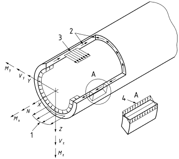
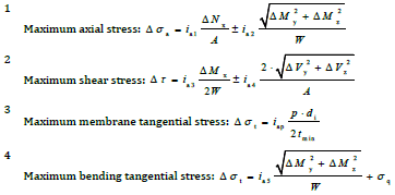

Button |
Property |
Description |
|
Force controlled action LC2 Membrane Stress A1 |
|
Allowable stress |
|
|
|
Force controlled action LC2 Membrane+Bending Stress A1 |
|
Allowable stress |
gm is specified in pipe properties |
|
|
Stepwise plastic deformation LC3 Force+deformation stress A2 |
|
Allowable stress |
|
|
|
Low
cycle fatigue |
|
Allowable stress |
ni - specified in temperature cycles and multiplied by service life from project settings. Equivalent number of full cycles should not be lower that lowest number of full cycles Nmin, that is specified in project settings and depending on pipeline type, that is specified in pipe properties. Project class is specified in pipe properties.
|
You can move the mouse over every table cell and see detailed report with equations and values used while calculating the result shown the cell. It will work if "show equations" option is checked.
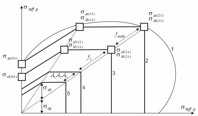
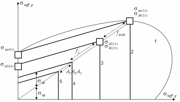
Full failure envelope
1 – real short-term failure envelope, 2 – idealized short-term failure envelope, 3 – idealized long-term failure envelope, 4 – non-factored design failure envelope, 5 – factored design long-term failure envelope
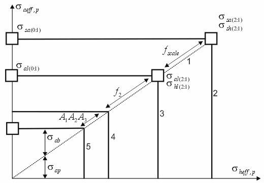
Simplified failure envelope
1 – real short-term failure envelope, 2 – idealized short-term failure envelope, 3 – idealized long-term failure envelope, 4 – non-factored design failure envelope, 5 – factored design long-term failure envelope
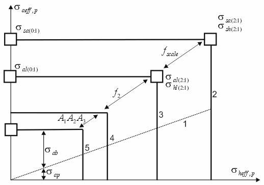
Simplified failure envelope for fittings and joints at r=1
1 – stress to pressure correlation line (2:1), 3 – idealized long-term failure envelope, 4 – non-factored design failure envelope, 5 – factored design long-term failure envelope
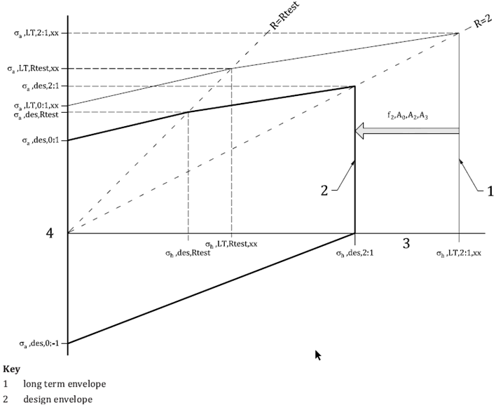
Simplified failure envelope for fittings and joints at r>1
1 – stress to pressure correlation line (2:1), 3 – idealized long-term failure curve, 4 – non-factored design failure curve, 5 – factored design long-term failure curve
Button |
Property |
Description |
|
Stress from weight loads Sheff |
Equivalent hoop stress from
weight loads |
Allowable from weight loads [Sh] |
For pipes |
|
Stress from weight loads Saeff |
Equivalent axial stress from
weight loads |
|
Allowable from weight loads [Sa] |
Factor For pipes when using full failure envelope:
For pipes when using simplified failure envelope:
For fittings at r≤1:
For fittings at r>1:
|
|
|
Stress from all loads in operating mode Sheff |
Analogous calculation, but from all loads in operating mode |
Allowable from all loads in operating mode [Sh] |
Analogous calculation, but factor
|
|
Stress from all loads in operating mode Saeff |
Analogous calculation, but from all loads in operating mode |
|
Allowable from all loads in operation state [Sa] |
Analogous calculation, but factor
|
|
|
Stress from all loads in cold mode Sheff |
Analogous calculation, but from all loads in cold mode |
Allowable from all loads in cold mode [Sh] |
Analogous calculation, but factor
|
|
Stress from all loads in cold mode Saeff |
Analogous calculation, but from all loads in cold mode |
|
Allowable from all loads in cold mode [Sa] |
Analogous calculation, but factor
|
|
|
Stress from all loads in test state Sheff |
Analogous calculation, but for test state |
Allowable from all loads in test state [Sh] |
Analogous calculation, but factor
|
|
Stress from all loads in test state Saeff |
Analogous calculation, but for test state |
|
Allowable from all loads in test state [Sa] |
Analogous calculation, but factor
|
Button |
Property |
Description |
|
Stress from weight loads |
Factor
For pipes when using full failure envelope:
For pipes when using simplified failure envelope:
|
|
Stress from all loads in operating mode |
Analogous calculation, but factor
|
|
Stress from all loads in cold mode |
Analogous calculation, but factor
|
|
Stress from all loads in test state |
Analogous calculation, but factor
|
Stresses calculation depends on options:
"Stress range from operation to cold" in Project Settings
Maximum f always 1.0 in Project Settings
During sustained stress calculation, the crossection area A and modulus of resistance Z wall thickness is reduced by corrosion allowance.
During sustained stress calculation, the crossection area A and modulus of resistance Z wall thickness is not reduced.
Button |
Property |
Description |
|
Stress due to sustained or occasional loads, Sl |
Occasional stress:
A - cross-section area, F - axial force, Mi - in-plane moment, Mo - out-plane moment, Mt - torsion moment, Z - moment of resistance L1 - sustained loads (W+P), L6 - operational loads (W+P+T), L11 - operational loads + occasional force-based loads (W+P+T+OCC) |
Allowable stress from sustained or occasional loads |
Sustained:
Occasional:
k - occasional k-factor Sh - hot allowable stress from material database Mf - Performance factor from pipe properties |
|
|
Stress range from between operation and (installation/cold) state, Se |
Stress range calculated between operation and installation mode. If option "stress range from operation to cold" is on, then between operation and cold mode.
|
Allowable stress range, Sa |
N - number of full cycles. Calculated by:
Information for calculation is got from temperature cycles |
|
|
Stress due to sustained in test state, Sl |
The same as stress due to sustained or occasional loads, Sl |
Allowable stress from sustained loads in test state |
|
Stresses calculation depends on options:
"Add axial force and torsion stress" in Project Settings
"Stress range from operation to cold" in Project Settings
Maximum f always 1.0 in Project Settings
Use maximum distortion energy theory=True/False/Maximum in Project Settings
Restrained/Unrestrained: Specify manually, Autodetect, Use START Smart Check in Project Settings
Pipeline type: Restrained, Unrestrained in Pipe Properties
Corrosion allowance and mill tolerance doesn't affect stresses in this code for all types of pipelines except risers.
For risers during stress calculation, the crossection area A and modulus of resistance Z wall thickness is reduced by corrosion allowance and mill tolerance.
Sustained, Operation, Expansion, Test stresses:

Start smart check:

Stresses from occasional loads:

Start smart check from occasional loads:

Button |
Property |
Description |
Hoop Stress |
|
|
|
Stress due to sustained or occasional loads, Sl |
Restrained: Not checked Unrestrained:
From occasional force-based loads:
F - axial force without Bourdon effect Start Smart Check:
From occasional force-based loads:
F - axial force with Bourdon effect A - cross-section area, Mi - in-plane moment, Mo - out-plane moment, Mt - torsion moment, Z - moment of resistance L1 - sustained loads (W+P), L6 - operational loads (W+P+T), L11 - operational loads + occasional force-based loads (W+P+T+OCC) |
Allowable stress from sustained or occasional loads |
Onshore Pipeline: Restrained:
Unrestrained:
Sy - Yield Stress from material database |
|
|
Stress due to operation loads, Sl |
Restrained:
F - axial force without Bourdon effect Unrestrained: Not checked Start Smart Check:
F - axial force with Bourdon effect |
Allowable stress from sustained or occasional loads |
Sy - Yield Stress from material database |
|
|
Stress range from between operation and (installation/cold) state, Se |
Stress range calculated between operation and installation mode. If option "stress range from operation to cold" is on, then between operation and cold mode.
|
Allowable stress range, Sa |
N - number of full cycles. Calculated by:
Information for calculation is got from temperature cycles |
|
|
Stress due to sustained in test state, Sl |
Restrained:
F - axial force without Bourdon effect Unrestrained:
F - axial force without Bourdon effect Start Smart Check:
F - axial force with Bourdon effect |
Allowable stress from sustained loads in test state |
Restrained:
Unrestrained:
|
Stresses calculation depends on options:
"Add axial force and torsion stress" in Project Settings
"Stress range from operation to cold" in Project Settings
Restrained/Unrestrained: Specify manually, Autodetect, Use START Smart Check in Project Settings
Pipeline location: Onshore Pipeline (BS PD 8010-1), Offshore Pipeline (BS PD 8010-2) in Pipe Properties
Pipeline type: Riser/landfall, Seabed including tie-in in Pipe Properties
Corrosion allowance and mill tolerance doesn't affect stresses in this code for all types of pipelines except risers.
Sustained, Operation, Expansion, Test stresses:

Start smart check:

Button |
Property |
Description |
Hoop Stress |
Onshore:
Offshore:
|
|
|
Stress due to sustained or occasional loads, Sl |
Onshore Pipeline (BS PD 8010-1): Restrained: Not checked Unrestrained:
Start Smart Check:
Offshore (BS PD 8010-2):
A - cross-section area, Mi - in-plane moment, Mo - out-plane moment, Mt - torsion moment, Z - moment of resistance |
Allowable stress from sustained or occasional loads |
Onshore Pipeline:
Offshore
Sy - Yield Stress from material database |
|
|
Stress due to operation loads, Sl |
Onshore Pipeline: Restrained:
F - axial force without Bourdon effect Unrestrained: Same as sustained Start Smart Check: Same as sustained Offshore: Same as for sustained loads |
Allowable stress from sustained or occasional loads |
Onshore Pipeline:
Offshore
Sy - Yield Stress from material database |
|
|
Stress due to sustained in test state, Sl |
Same as sustained |
Allowable stress from sustained loads in test state |
Same as sustained, but
|
Stresses calculation depends on options:
"Add axial force and torsion stress" in Project Settings
"Stress range from operation to cold" in Project Settings
Restrained/Unrestrained: Specify manually, Autodetect, Use START Smart Check in Project Settings
Corrosion allowance and mill tolerance doesn't affect stresses in this code for all types of pipelines except risers.
Sustained, Operation, Expansion:
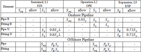
Start smart check:

Button |
Property |
Description |
Hoop Stress |
|
|
|
Stress due to sustained or occasional loads, Sl Allowable stress |
Onshore Pipeline: Restrained: Not checked Unrestrained:
Start Smart Check:
Offshore (Ch.11):
A - cross-section area, Mi - in-plane moment, Mo - out-plane moment, Mt - torsion moment, Z - moment of resistance |
|
Stress due to operation loads, Sl |
Onshore Pipeline: Restrained:
F - axial force without Bourdon effect Unrestrained:
Start Smart Check:
Offshore: Same as for sustained loads |
Expansion Stress |
|
|
Stress from thermal expansions, weight, and seismic wave propagation effect |
Two checks are performed. First check:
Second check:
F - Axial force thermal expansions, pressure Bourdon effect, weight, and seismic wave propagation effect E - Elastic modulus t - Pipe wall thickness D - Pipe outside diameter |
Bend stress intensification and flexibility factors calculated using equations:


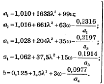
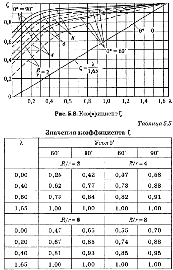
Button |
Property |
Description |
|
Equivalent stress from weight loads |
Equivalent stress from weight loads (first stage of analysis)
|
Allowable stress from weight loads |
|
|
|
Equivalent stress from all loads in operating mode |
Equivalent stress from all loads in operating mode (second stage of analysis) In accordance with RD 10-249-98, section 5.2 for low-temperature pipelines, stress in operation and cold mode from all loads is not calculated or assessed.
|
Allowable stress for all loads in operating mode |
|
|
|
Equivalent stress from all loads in cold mode |
Equivalent stress from all loads in cold mode (fourth stage of analysis) In accordance with RD 10-249-98, section 5.2 for low-temperature pipelines, stress in operation and cold mode from all loads is not calculated or assessed.
|
Allowable stress for all loads in cold mode |
|
|
|
Fatigue fracture factor |
For analyses based on section 5.1 (fatigue strength analysis) total fatigue fracture factor (third stage of analysis) is equal to
|
|
Design stress amplitude |
Design stress amplitude (p. 5.2.7.3). In accordance with RD 10-249-98, section 5.2 for high-temperature pipelines, fatigue strength analysis is not done, so fatigue fracture factor is not calculated
|
Allowable stress amplitude |
Allowable stress amplitude (p. 5.2.7.3). The design number of cycles couldn't be less than 3000. In accordance with RD 10-249-98, section 5.2 for high-temperature pipelines, fatigue strength analysis is not done, so fatigue fracture factor is not calculated
|
[σ]op - allowable stress at operation temperature Top, [σ]20 - allowable stress at normal temperature
Button |
Property |
Description |
 |
Equivalent stress from weight loads |
Equivalent stress from weight loads (first stage of analysis) |
Allowable stress from weight loads |
1.1[σ]op |
|
 |
Equivalent stress from all loads in operating mode |
Equivalent stress from all loads in operating mode (second stage of analysis) Meeting strength conditions from all loads in operation and cold (if there is pre-stretch) state, required only for pipes and not required for bends and tees (stub-ins) |
Allowable stress for all loads in operating mode |
1.5[σ]op For low temperature piping bends, tees and reducers is not checked ( "No" ) |
|
 |
Equivalent stress from all loads in cold mode |
Equivalent stress from all loads in cold mode (third stage of analysis) Meeting strength conditions from all loads in operation and cold (if there is pre-stretch) state, required only for pipes and not required for bends and tees (stub-ins) |
Allowable stress for all loads in cold mode |
1.5[σ]20. For low temperature piping bends, tees and reducers is not checked ( "No" ) |
|
 |
Equivalent stress from weight loads in test state |
Equivalent stress from weight loads in test state |
Allowable stress from weight loads in test state |
1.5[σ]test For tees, bends and reducers 1.5([σ]20+[σ]test) |
|
 |
Stress range from hot to cold mode |
Stress range from hot to cold mode |
Allowable stress range |
Minimum of the two values 1.5([σ]20+[σ]op) and
|
[σ]op - allowable stress at operation temperature Top, [σ]20 - allowable stress at normal temperature
Please refer to Thermoplastic Piping Stress Analysis
Stress table for SNIP 2.05.06-85 looks like this:

Button |
Property |
Description |
|
Hoop stress, design and allowable |
For any pipelines, section 8.22 formula (12), section 8.63 formula (59) SNIP 2.05.06-85:
|
Hoop stress, operation and allowable |
For buried pipelines, condition section 8.26 formula (30) SNIP 2.05.06-85 is used:
|
|
Longitudinal axial stress, design and allowable |
section 8.24 formula (15) SNIP 2.05.06-85:
N - force from the analysis of design loads taking into account load safety factors and pressure thrust force |
|
Longitudinal fiber stress (calculated) |
Maximum fiber equivalent stress in cross-section edge fibers, calculated separately for compressed and stretched cross-section areas, followed by calculating the maximum value
Longitudinal stress is calculated based on conditions determined by design load analysis (taking into account load safety factors)
Longitudinal stress is calculated based on conditions determined by standard load analysis (without taking into account load safety factors)
where
|
|
Design resistance R1 |
Design resistance for tensile strength
|
|
Design resistance R2 |
Design resistance for yield strength
|
No. |
Note |
Code |
Description |
N218 |
Temperature range exceeds limit |
Strength
condition not met: |
|
N219 |
Insufficient wall thickness |
Strength
condition not met: |
|
N221 |
Structure does not meet strength conditions |
One of strength conditions not met:
|
|
N265 |
Failed stress check from pressure and weight loads |
All others |
Strength condition not met: S > Sallowable |
N268 |
Failed the stress check in operation condition |
All others |
Strength condition not met: S > Sallowable |
N269 |
Failed the stress check in cold condition |
All others |
Strength condition not met: S > Sallowable |
N284 |
Failed the fatigue strength check |
All others |
Fatigue failure condition not met S > Sallowable |
N676 |
Failed wall buckling check in test condition |
All others |
Strength condition not met: S > Sallowable |
N677 |
Failed wall buckling check in operation condition |
All others |
Strength condition not met: S > Sallowable |
N678 |
Failed wall buckling check in cold condition |
All others |
Strength condition not met: S > Sallowable |
After analysis: Output > Piping Stress