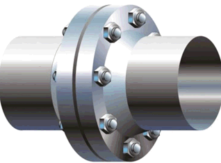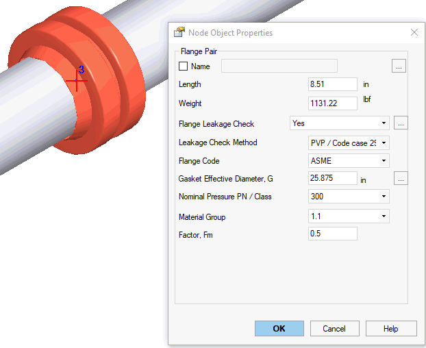


Flange pair is modeled same way as valve. Flange weight is considered the same as for a valve. Flange leakage check is automatically done when the "check leak resistance" flag is checked.


Property |
Description |
Name |
Element name. If checked then it shown in 3D view |
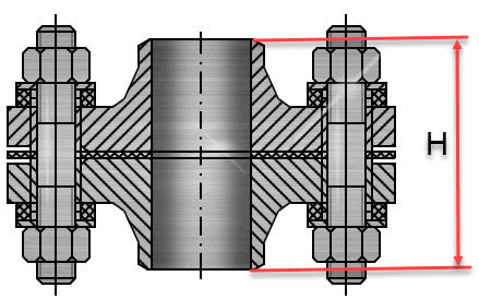
Length, H |
Full flange pair assembly length |
Weight |
Flange pair assembly weight with bolts and nuts without insulation and product weight. Product and insulation weight are calculated automatically based on adjoining pipes. |
Flange leakage check |
Flange leakage check will be done if this option is selected |
Leakage Check Method |
Choose one of flange leakage check methods Insulation joint (Insulation Kit) stresses are checked according to manufacturers recommendations using 72% or 75% of yield stress allowable:
Following equation for 72%:
Following equation for 75%
|
Flange Code |
Choose flange code: GOST, ASME B16.5, EN 1092-1 |
Gasket Effective Diameter, G |
G - Diameter at location of gasket load reaction per ASME B 16.20 & ASME Sec. VIII Div. 1, Appendix 2, Table 2-5.2 For ASME B16.5, EN 1092-1 flanges G value should be calculated using following equations:
OD – Outer diameter of gasket ID – Inner diameter of gasket b0 - Basic gasket seating width as given in Table 2-5.2 of ASME VIII Div. 1, Appendix 2 b – Basic gasket width
Cb=0.5 for U.S. customary calculations, 2.5 for SI calculations
|
Nominal Pressure PN / Class |
Nominal Pressure PN for GOST and EN 1092-1 flanges and Class for ASME B16.5 flanges |
Material Group |
Flange material group according to the selected code ASME B16.5-2020
EN 1092-1:2013
|
Factor Fm |
Factor Fm used in Code Case 2901 (PVP) method according to following table
|
Bolt Area, Ab Bolt Circle Diameter, C |
|
Bolt Material |
Choose Material From database |
To insert a flange, select the desired node and use the menu option: Insert > Insert Flange Pair
or press the  toolbar icon.