
These supports are gaining popularity and are often used instead of variable spring supports. They are modeled as rigid rod hangers hung over a rotating block with a P value load hung on the end (fig. 1). During vertical displacement, supporting force P remains constant. However, this structure is not used in practice due to its large size.
Fig. 1
Modern constant spring support structures usually use a spring-lever mechanism (fig. 2), which uses pre-stretch adjustments to ensure nearly constant supporting force in a fixed range of vertical displacement (fig. 3).
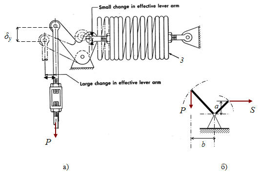
Fig. 2
Fig. 3
This support does not use any external restraints. Supporting force is applied to the support's node, which is input as three projects on the global coordinate axes Fx, Fy, Fz. See "custom restraints"
Property |
Description |
Name |
Element name. If checked then it shown in 3D view |
Weight |
Support weight |
Series |
|
Rod number |
Parallel installed hanger rod numbers (1 or 2) |
Support number |
Parallel installed support numbers (1 or 2) |
Rod length |
Rod length, used for considering the pendulum effect |
Test state mode |
In some cases, springs may be temporarily locked during testing, which must be taking into account in the analysis |
Friction factor |
|
Force along the X axis |
Support force project along the global X axis. Automatic rod selection is not done |
Force along the Y axis |
Support force project along the global Y axis. Automatic rod selection is not done |
Force along the Z axis |
Support force project along the global Z axis. If 0, automatic constant spring support selection is performed. |
To insert an element, select the desired node and use: Insert > Insert Restraint > Constant Spring Support / Insert > Insert Restraint > Constant Spring Hanger
or press the  toolbar icon.
To view properties of an existing element:
Double-click the element in the 3D view
Select the
element and press the  toolbar icon