
Due to the ability to use custom restraints with various directions and combinations of restraints, having various properties, almost any real restraints can be modeled in START-PROF, including supports considering friction, hangers considering additional lateral forces when not turned on, vessel and equipment stub-ins, etc.
Custom restraints are modeled by any number of various types of external restraints, placed in a node at various angles in order to prevent displacement and rotation angles. Rotational and Linear restraints are used in START-PROF, having the following properties:
Rigid double-acting
Rigid single-directional
Spring
Friction
Rod
Restraints can be linear or rotational. Linear Restraints - restrict pipe cross-section displacement along a certain axis, Lateral Restraints - restrict pipe cross-section rotation around a certain axis. Examples are given in the table below:
Linear restraints restrict node displacement, but not rotation.
Example 1: Fig. 1 shows a piping with a single linear rigid restraint, which completely prevents pipe-cross section vertical displacement, but does not restrict rotation.
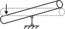
Fig. 1
Example 2: Fig. 2 shows a piping with two linear elastic restraints, which flexibly restrict displacement of a pipe-cross vertically, but do not restrict rotation.
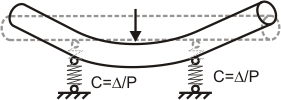
Fig. 2
Lateral rigid restraints restrict node rotation around a certain axis, but do not restrict displacement.
Example 1: Fig. 3 shows a piping with a single lateral rigid restraint, which restrict rotation of the pipe cross-section. If a bending moment is applied from the left, the pipe will bend only at the section between the point where the bending moment is applied and the lateral restraint. It will not bend to the right of the restraint. However, there is no restriction on displacement in any direction. These kind of restraints are referred to as a "floating anchor" - in other words, a seal preventing rotation but not linear displacement along the coordinate axes.
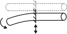
Fig. 3
Example 2: Lateral restraints are rare in real structures. They are usually combined with linear restraints. For example, fig. 4 shows a piping with a single linear rigid restraint, which restricts vertical pipe-cross section displacement, and a lateral rigid restraint, which restricts rotation of the pipe cross-section. In this case, if a force is applied to the left of the lateral restraint, the pipe will bend only at the section between the point where the force is applied and the lateral restraint. It will not bend to the right of the restraint.
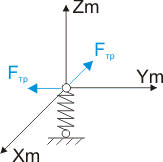
Fig. 4
Example 3: Lateral restraints, as well as linear restraints, can be elastic - in other words, flexibly restrict cross-section rotation. Fig. 5. shows a structure with a single linear rigid restraint, which restricts vertical pipe cross-section displacement, and a lateral elastic restraint, which flexibly restricts rotation of the pipe cross-section. This structure is something between that shown on fig. 1 and fig. 4.
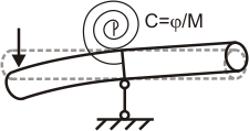
Fig. 5
Various linear and lateral restraint types are described below.
Linear rigid double-acting restraints restrict node displacement in both sides along the axis (fig. 6).
Lateral rigid double-acting restraints restrict node rotation in both directions along the axis (fig. 3).
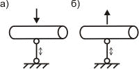
Fig. 6
Linear rigid single-directionalrestraints restrict node displacement only in one direction along the axis. They are disabled during displacement in the other direction. For example, sliding supports restrict downward displacement (fig. 7.a), but not upward - the pipe is removed from the support and the restraint is disabled (fig. 7.b).
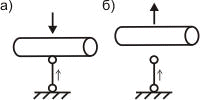
Fig. 7
Linear (fig. 8) and lateral (fig. 5) elastic restraints are springs which always function as double-acting restraints (never disabled). Characterized by flexibility C.
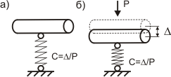
Fig. 8
Friction restraints are not input by the user but rather set automatically to account for friction in supports.
If the reaction in a friction restraint is less than the frictional force limit Ffr, then the friction restraint automatically becomes rigid - restricts pipe slide.
If the reaction in a friction restraint is more than the frictional force limit Ffr, then there is no restraint. Frictional force equal to Ffr=R∙μ (fig. 9,а) is applied in the opposite direction of the node. Where R - vertical reaction creating the frictional force, μ - friction factor.
When the frictional force direction is known (for example for guiding supports), one linear friction restraint in the direction of frictional force is inserted. If the direction is unknown, two perpendicular linear friction restraints in the sliding plane FX and FY (fig. 9.b) are inserted, for example along and across the pipe axis. In this case, one Ftr frictional support is calculated as a geometrical sum of all reactions of this friction (fig. 9.b).
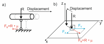
Fig. 9
Fictitious restraints are not input by the user but rather set automatically to account for the pendulum effect (additional horizontal reactions Fd, occurring with hanger deflection from vertical position by a certain angle α). If reactions equal hanger force projections on the horizontal plane, Fd=R∙Sin(α) and seek to return it to vertical position. Since α is a small angle, it can be considered that Sin(α)=Δ/L, and therefore Fd=R∙Δ/L. Rod length L is input by the user, while displacement Δ is calculated.
Two perpendicular linear fictitious restraints FX and FY in the horizontal plane are always inserted (fig. 10.b). The lateral component of the horizontal hanger reaction Ffict is calculated as a geometric sum of all restraint reaction.
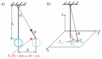
Fig. 10
The direction of each restraint is set as a vector restricting movement (i.e., direction in which displacement is restricted). Vector direction is set along one of the local or global coordinate axes, or as three angles between reaction vectors and global or local coordinate axes.
Exact restraint reaction direction (straight or reverse) must be set only for single-directional restraints or restraints with different gaps to the left and right, since these restraints work differently depending on the displacement direction. In other cases, direction is not relevant (fig. 11,а.b).
To determine restraint reaction direction, the coordinate system is symbolically placed inside the relevant node. Angles are set as follows:
The angle between the restraint reaction vector and the coordinate axis is always sharp
The angle value is positive if the angle is between a restraint reaction vector and a positive direction of the coordinate axis (fig. 11.a), and negative if the angle is between a restraint reaction vector and a negative direction of the coordinate axis (fig. 11.b). For example, -30° angle from the Z axis signifies a 30° angle between the restraint reaction direction and the negative direction of the Z axis (see examples 3, 4 and 5)
When the reaction direction and coordinate axis follow the same line (angle is 0), the angle is set as 0° when the coordinate axis is positive, and 180° when the coordinate axis is negative (see examples 1 and 2)
The sum of the squared cosines of all angles should equal 1 (if this condition is not met, there is a mistake with the angles). This condition is checked automatically.
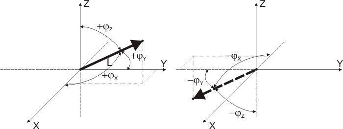
Fig. 11
Examples:
Example no. |
Angles |
Diagram |
Description |
||
|---|---|---|---|---|---|
X |
Y |
Z |
|||
1 |
90 |
90 |
0 |
|
Restraint reaction is directed vertically up (along the positive direction of the Z axis) |
2 |
90 |
90 |
180 |
|
Restraint reaction is directed vertically down (along the negative direction of the Z axis) |
3 |
90 |
60 |
30 |
|
Restraint reaction is directed up at a 30° angle to the Z axis |
4 |
90 |
60 |
-30 |
|
Restraint reaction is directed down at a 30° angle to the Z axis |
5 |
-60 |
90 |
30 |
|
Restraint reaction is directed up at a 30° angle to the Z axis |
Example:
In a sliding support, a single-directional restraint works only for downward displacement (against the Z axis) and is disabled for upward displacement (along the Z axis). This restraint reaction is directed up (along the Z axis). Therefore, to insert this kind of restraint, select the "-Z" option (since the support restricts downward displacement) or input angles (90,90,0) corresponding to a downward directed restraint reaction vector.
To simplify the placement of restraints, START-PROF contains a set of standard supports. First, these supports already contain the required combination of restraints; second, they automatically position the restraint directions based on the direction of local element axes. Restraints in standard START-PROF supports are described below.
The Xm axis is directed along the element axis, Zm - perpendicular to the pipe axis upward, Ym - perpendicular to the pipe axis and the Zm axis.
The following symbols are used to represent restraint types and properties:
 - rigid linear
double-acting restraint
 - rigid linear
single-directional restraint. Restraint
reaction direction indicated with an arrow
 - rigid lateral
double-acting restraint
 - elastic lateral
restraint
 - elastic linear
restraint
friction (frictional force) and fictitious restraints indicated with arrows

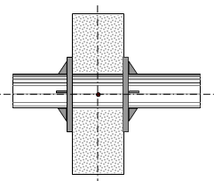
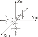
A fixed anchor restricts linear displacement and rotation in all directions. Two types of fixed anchors are shown in diagrams:
Welded structure consisting of two fixed anchors spaced at a distance of approximately 2÷4 diameter; stops rotation. In practice, this structure is usually one long support.
Shield design anchor. The piping passes through a round opening in a concrete wall, and flanges are closely welded on both sides of the concrete. This is most commonly used in district heating networks.
This support is modeled as three linear and three lateral rigid double-acting restraints.
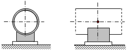
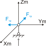
A sliding support rigidly attached to a pipe, the support plate at the bottom, which transfers the load from the piping to supporting structures (modeled as a rigid base). At the point of contact between the plate and the rigid base, there is a friction surface. The support restraints downward piping displacement, and is disabled during upward displacement. If an active support is displaced in the horizontal plane, a frictional force is created on the sliding surface, directed opposite to the displacement direction.
This support is modeled as one vertical single-directional linear rigid restraint and two frictional restraints in the horizontal plane.
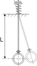
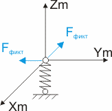
The main element is springs or spring chains. These are used to allow thermal expansion and control piping stress using forced spring compression. This support applies one elastic vertical restraint with a flexibility C and two fictitious restraints in the horizontal plane, which take into account the rod rotation effect.

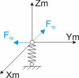
The main element is springs or spring chains. These are used to allow thermal expansion and control piping stress using forced spring compression. This support applies one elastic vertical restraint with a flexibility C and two frictional restraints in the horizontal plane

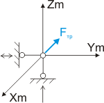
Guiding support structure allows displacement along the piping axis. It differs from a resting support in the number of stops restricting displacement perpendicular to the pipe axis in the horizontal plane. This support restricts downward displacement, but is disabled during upward displacement. Longitudinal displacement is accompanied with a frictional force on the sliding surface.
This support is modeled with two linear rigid restraints (vertical single-directional and horizontal double-acting) and a friction restraint along the pipe axis.
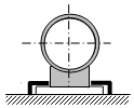
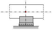
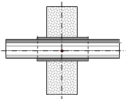
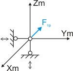
This support is similar to a guiding single-directional support, but is not disabled for upward displacement. Can be used for modeling a shell.
This support is modeled with two linear rigid restraints (vertical double-acting and horizontal double-acting) and a friction restraint along the pipe axis.

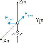
Vertical rigid rod hanger restricts downward pipe displacement, but is disabled for upward displacement. When the hanger is displaced from the vertical position, force projection on the horizontal plane are created and seek to return the hanger to the original position.
This support is modeled by one vertical linear single-directional restraint and two fictitious restraints in the horizontal plane.
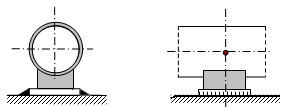
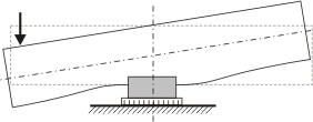
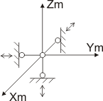
This support rigidly attached to a pipe, the support plate at the bottom, which transfers the load from the piping to supporting structures. The support plate is welded to a rigid base.
This support restricts upward and downward displacement, as well as along and perpendicular to the pipe axis. Pipe cross-section rotation resistance is usually insignificant, since the support length (size along the pipe axis) is usually comparable to the pipe cross-section dimensions (1 diameter). So lateral restraints (restricting bending and rotation) are negligible.
This support applies three double-acting linear rigid restraints.

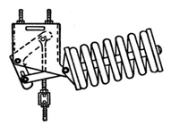
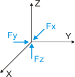
Constant spring supports are currently very popular and are often used instead of elastic supports. The ideal constant spring support structure is a rigid rod hanger over a rotating unit, with a P value load on the end. The supporting force P transferred to the piping remains constant during vertical piping displacement. But this structure is not used in practice due to its bulky dimensions. In modern structures, a spring-lever mechanism is usually used as a constant spring support, which, with adjusting of spring compression, ensures practically constant supporting force in a fixed range of possible vertical displacements.
This support does not apply any restraints. Supporting forces Fx, Fy, Fz are applied in the node where this support is placed.
Unfortunately, it is impossible to model all real restraint structures as a set of START-PROF supports. So it is often necessary to create a custom custom restraint. Examples of custom restraints are given below:

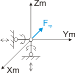
If a support contains a long sleeve in a concrete wall (more than 2÷4 diameters), it restricts rotation. Displacement along the pipe axis also creates frictional force of metal on metal.
This support should be modeled using a custom restraint with two (vertical and horizontal) double-acting linear rigid restraints, as well as two lateral rigid restraints restricting rotation perpendicular to the pipe axis.
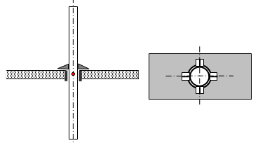
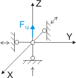
A guiding support can be placed on a vertical piping riser. The pipe passes through a round opening (sleeve) in the ceiling, which restricts lateral displacement in the horizontal plane. Four support brackets are welded to the pipe to prevent downward displacement.