
Read about START-PROF pipe stress analysis software
The correct specification of cylindrical shell elements temperature along the column height is important to get the realistic column thermal expansion values. It is needed to get the correct nozzle movements and therefore realistic expansion stresses in the piping system, connected to the column.
The column elements temperature should be based on the known temperature values of connected outlet lines. Only big diameter nozzles that have a significant effect on the temperature should be taken into account. Small nozzles are ignored.
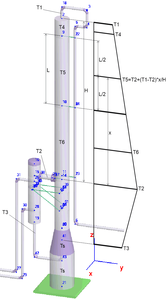
For example, we have 3 nozzles connected to the column (2, 37, 41 on the picture below) with temperatures 40, 250, 20 and several supports (9,10,11, 46, 52, 20, 21). The temperature for each cylindrical shell should be calculated as temperature at the center of the element using the linear interpolation between nearest nozzles. For example the temperature for cylindrical shell 9-10 (T5) can be obtained by equation:

Where
T2 - Temperature of the upper nearest column nozzle
T1 - Temperature of the lower nearest column nozzle
x - Distance between lower nearest nozzle and the center of the cylindrical shell 9-10
H - Distance between upper and lower nearest column nozzles
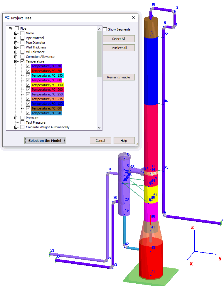
This procedure should be done for both operating, design and other operating mode temperatures.
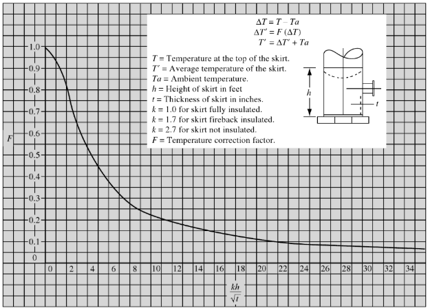
The skirt temperature Ts (20-21) can be obtained as average temperature between the ambient temperature and temperature at the top of the skirt. The following equation also recommended in the literature (for example "Piping and Pipelines Assessment Guide" By Keith Escoe):
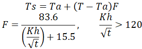
Ta - Ambient temperature
T - Temperature at the top of the skirt
K - Insulation constant. K=1.0 for fully insulated skirt, K=1.7 for firebrick insulated, and K=2.7 for non-insulated skirt
h - Skirt height
t - Skirt wall thickness
The column and column nozzles (2, 37, 38, 41) are modeled similar to vertical pressure vessels using cylindrical shell and nozzle element. It is quite easy procedure, so we will not show it here.
When adding the seismic, wind, show, and ice loads, they should be placed on both piping system and column cylindrical shell elements.
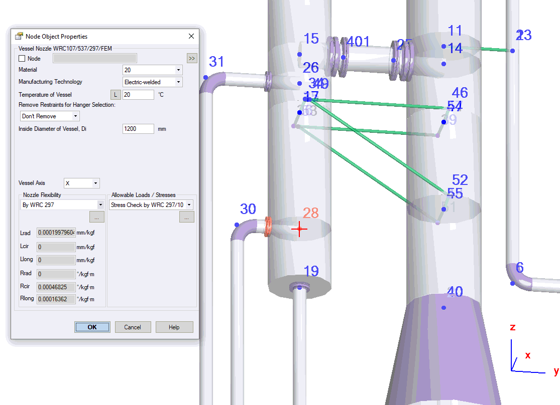
Allowable loads for the column nozzle are provided by equipment vendors and specified in the nozzle element properties:
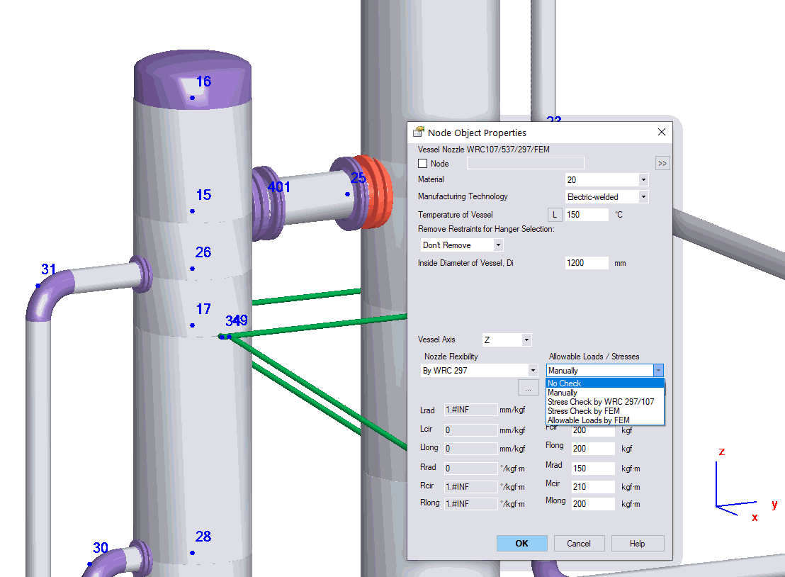
If allowable loads exceed the allowable values, then you can switch to WRC 107/537/297 stress check
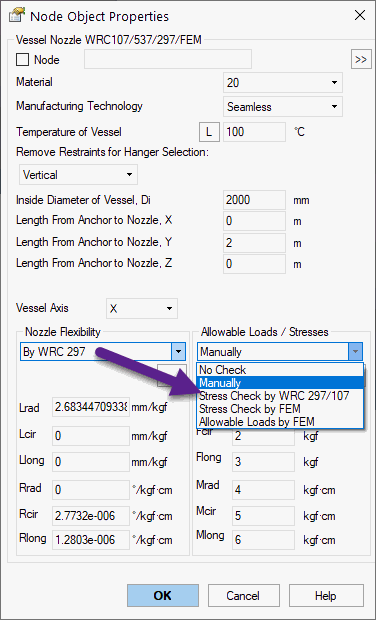
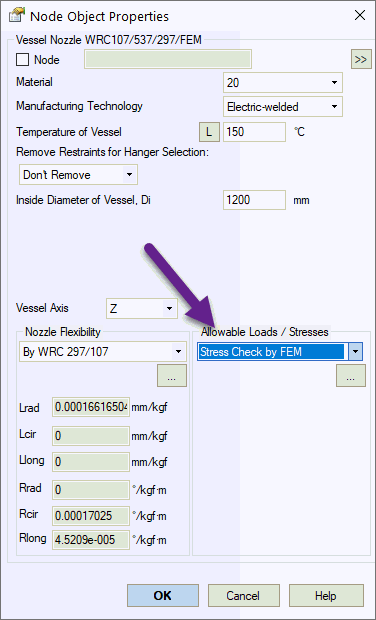
If WRC 107/537/297 can't be used due to non-standard geometry, limits of applicability violated, or other reasons, then switch to stress check by FEM (Finite Element Analysis), that is performed using integration with PASS/Nozzle-FEM software.
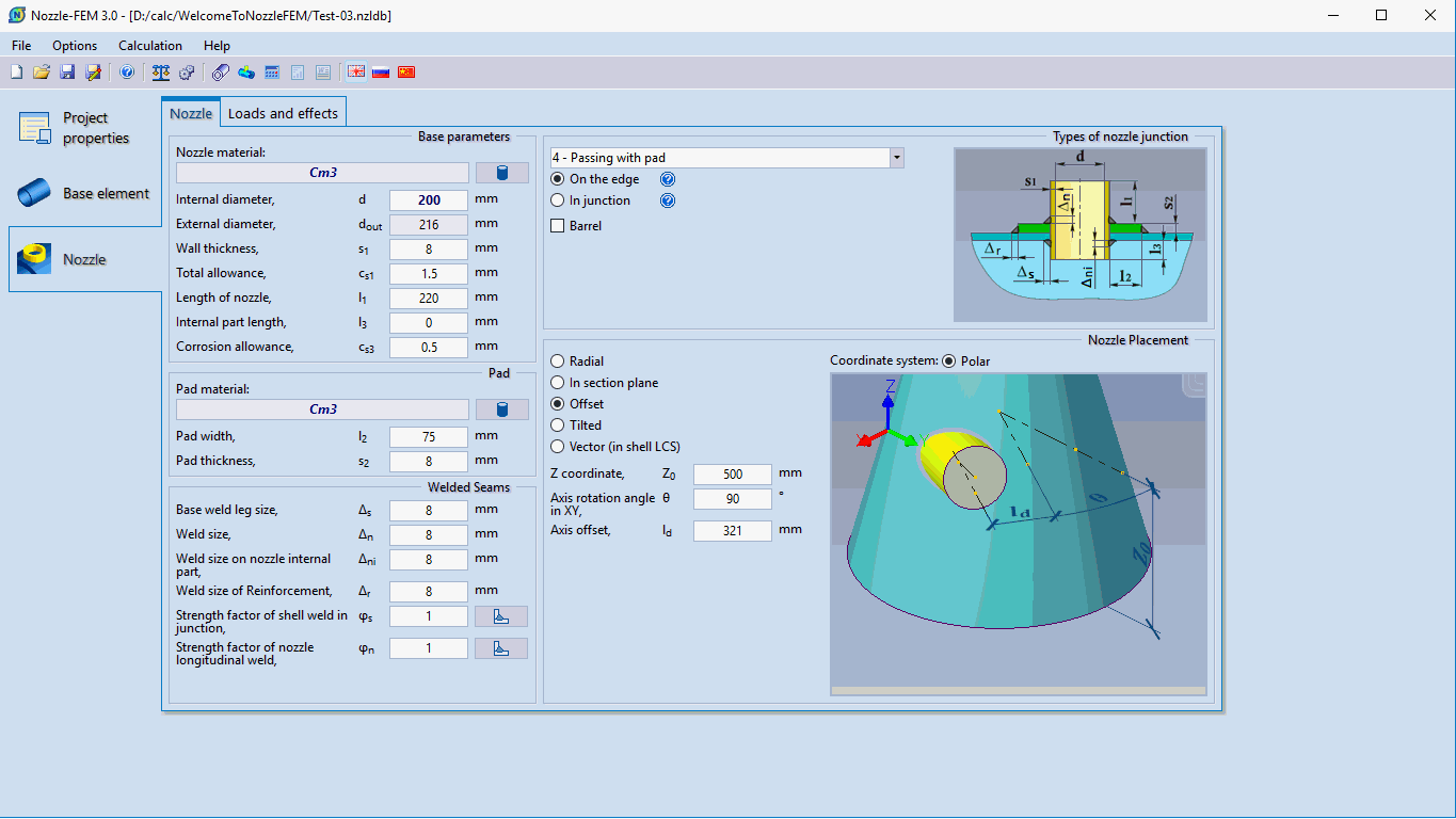
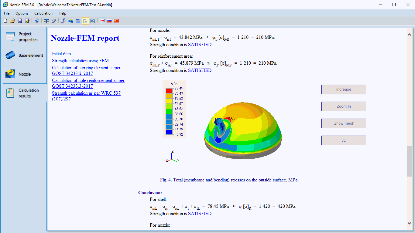
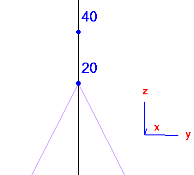
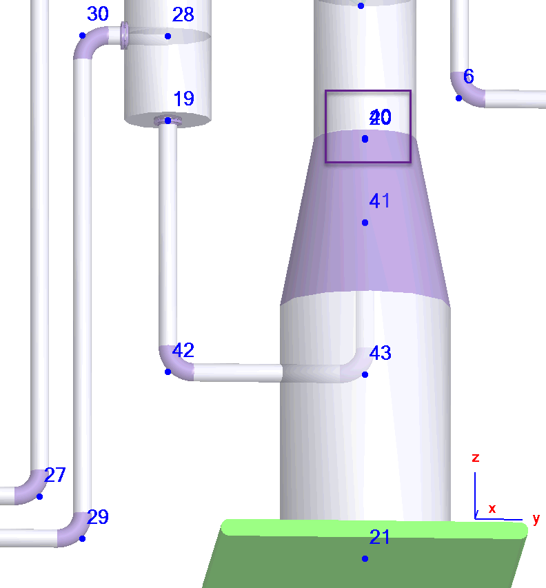
To model the connection between column and skirt, add the additional node 40 near the node 20 at the distance of 1 mm. Insert the pipe 20-21 into the node 20 (skirt), add fixed anchor into the node 21, reducer to the node 20, and the pipe 40-41 (column bottom). Connect pipe 41-43 to the node 41 and insert the nozzle element.
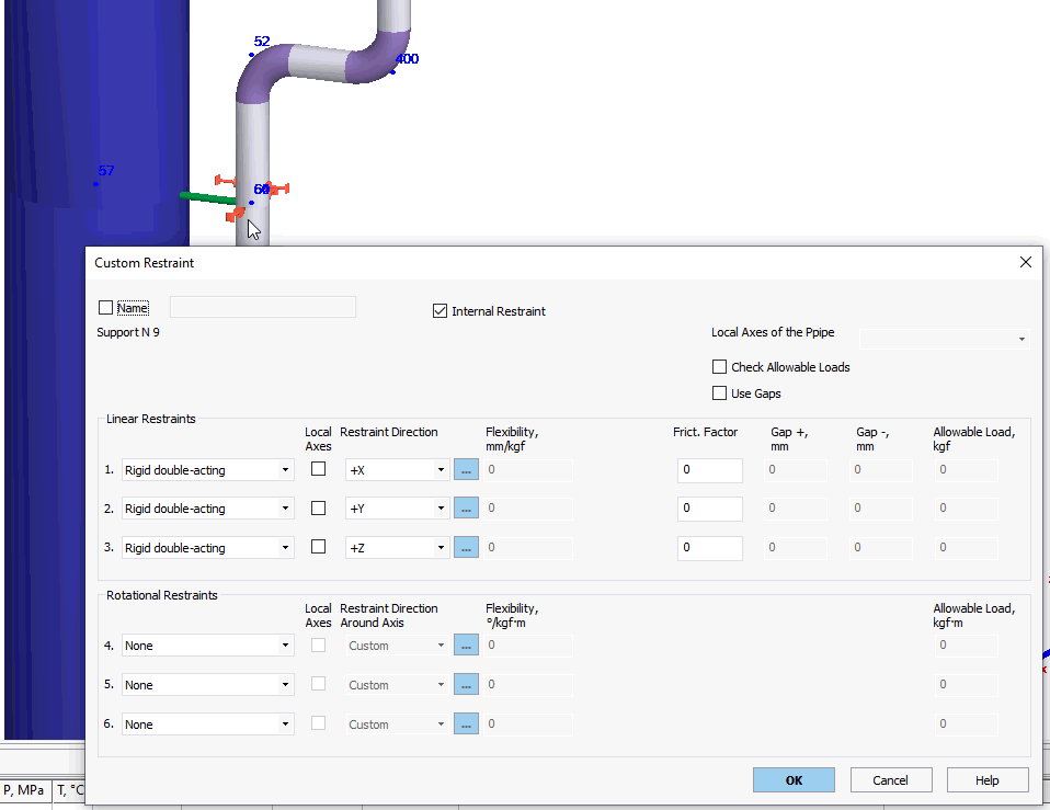
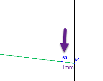
The pipes are connected to the column elements. The upper support is taking the vertical and part of horizontal piping weight and should be placed as near as possible to the nozzle. It is modeled using rigid element (57-54), connected to the column (node 57). To exclude rotational restraints, insert the internal restraint in 1 mm near the node 54 with three double-acting rigid restraints.
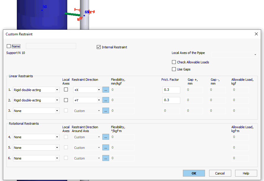
Other supports are guide supports. It is modeled using the rigid element too, but internal restraint should have two rigid double acting restraints in horizontal direction.
If the pipe weight is too great, then also additional variable spring hangers connected to the column can be added to hold the part of the weight loads.
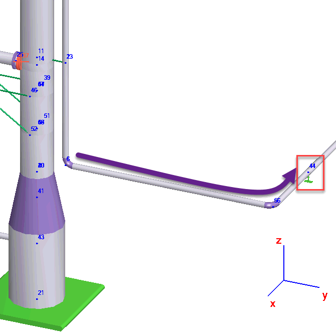
The first resting support on the horizontal pipe should be at greater distance to provide the enough thermal expansion and avoid the compression internal forces in the vertical pipe than can lead to buckling.
Set the reboiler body temperature as average temperature between inlet and outlet nozzles.
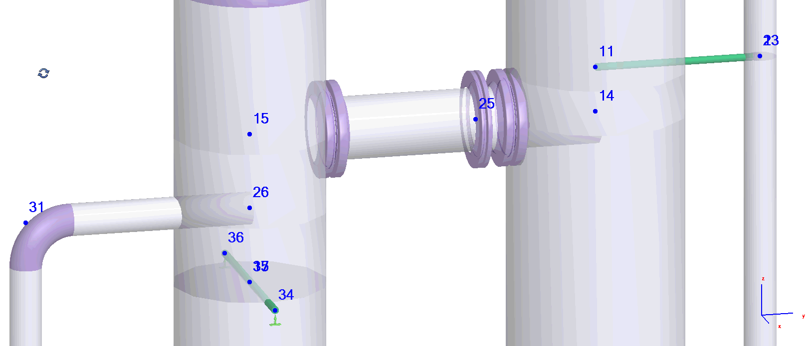
If reboiler is supported by an independent structure, then add two rigid elements into the node 17 and place variable spring supports (or other type) into the nodes 34 and 36. If reboiler has 3 or 4 lugs, then add more rigid elements and supports.
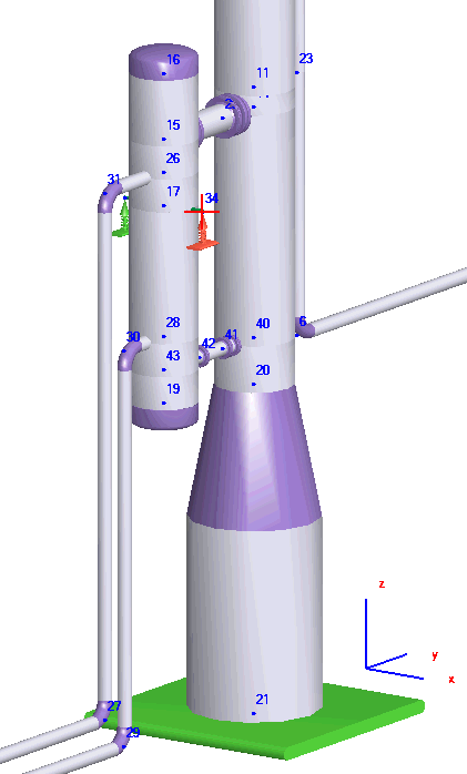
Reboiler nozzle element can be placed into the node 15, column nozzle into the node 14. Nozzles will be automatically modeled using rigid element, see description of the nozzle element.
If the reboiler is supported by the column, then the supporting structure can be modeled using the rigid elements or beam elements
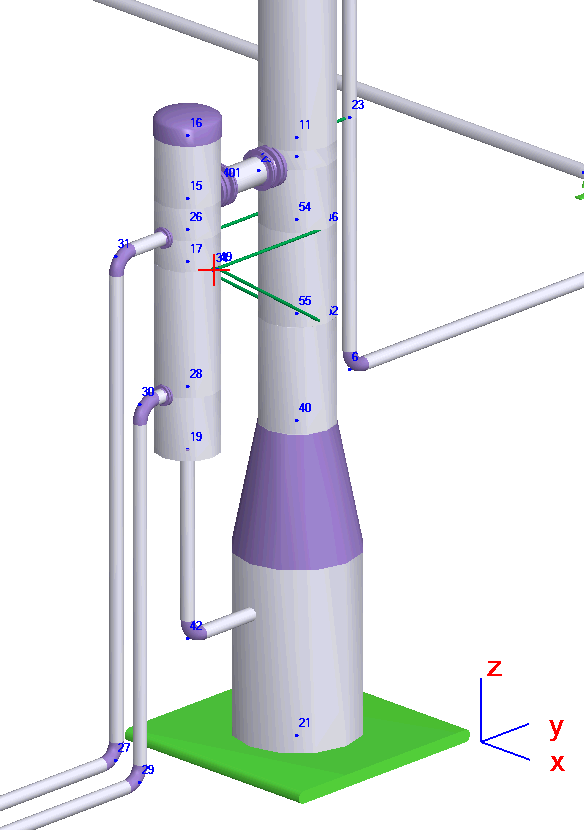
Flange elements should be checked for leakage (nodes 401, 27).
