
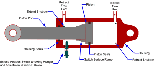
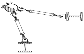
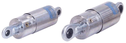
Snubbers are usually used for reducing the displacements, stresses and support loads from Earthquake events. There are two types of snubbers: hydraulic and mechanical.
Snubbers doesn't resist to the thermal displacements of piping system and doesn't reduce the piping flexibility. But in case of quickly applied occasional load, snubbers instantaneously form a practically rigid restraint. So for sustained and thermal loads snubber acts as very flexible restrain, but for dynamic loads it "lock-up" and acts as a rigid restraint. When the dynamic load has dissipated, the snubber unlocks and again works like very flexible restraint.
Snubbers considered as "locked" in seismic analysis, dynamic analysis, and in all occasional operating modes with enabled "Snubbers Active" flag. Snubbers considered as "unlocked" in all operating modes, force-based modes with disabled "Snubbers Active" flag, and also for snow and ice loads. For wind loads it depends on the snubbers "Active" flag in project settings dialog.
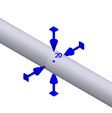
In START-PROF snubber object allows to add 6 restraints: 3 linear and 3 rotational.
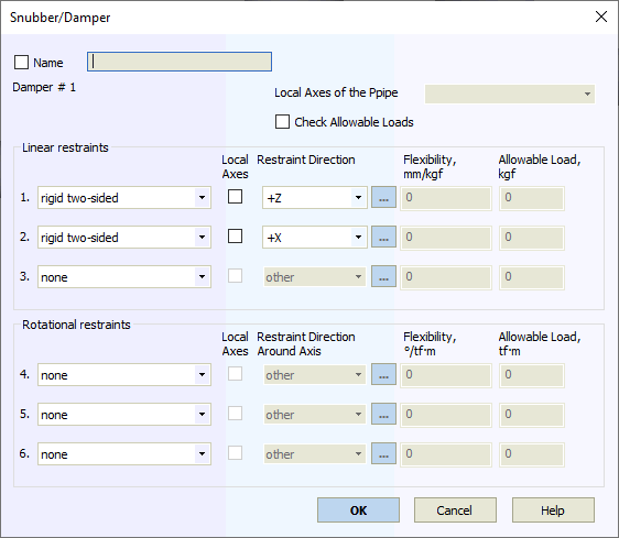
Property |
Description |
Name |
Element name. If checked then it shown in 3D view |
Weight |
Support weight (the part of the weight that is applied to the pipe as a load) |
Restraint type |
One of 2 types: rigid double-acting, and spring. "No" indicates absence of a restraint |
Element local axes |
The local axes of the selected element will be used as restraint local axes Xm, Ym и Zm |
Local axes |
If not checked, allowable loads are set for global coordinate axes (X,Y,Z); if checked, they are for local axes of the adjoining element (Xm,Ym,Zm). All restraints must be mutually perpendicular.
If "other" is selected, any restraint direction can be input
Restraint direction is modeled with three angles between the restraint direction (vector) and global coordinate axes. Minutes are indicates as tenths of a degree (up to two decimal points). For example, 30.25 indicates 30° 15'. For positive angles, "+" need not be written. More...
If the restraints contains at least one single-directional restraint in local coordinates or gaps, the element whose local axes are used as the restraint local axes must be indicated (required for correctly determine the restraint direction). |
Restrain displacement along axis |
Select direction along which displacement is restrained. +/- is irrelevant for double-acting and spring restraints (in the absence of gaps). If gaps are present in double-acting restraints, selecting the positive direction is recommended. For single-directional restraints, +X indicates that displacement in the positive direction of the X axis is restricted, and allowed in the negative. Likewise, -X indicates the opposite. |
Restrain rotation around axis |
Select direction around which rotation is restrained. |
Flexibility |
Spring restraint flexibility |
Check allowable loads |
If "Check allowable loads" option is checked, START-PROF automatically checks allowable load values against analysis results. If allowable values are exceeded, the corresponding warning is displayed |
Allowable load |
Allowable load in the restraint direction |
To insert an element, select the desired node and use: Insert > Insert Restraint > Snubber